< Home

Configuring Service PWs

Context

Service PWs are classified into primary PWs, secondary PWs, bypass PWs, and switching PWs when a multi-segment PW is configured. PW redundancy supports the Independent or Master/Slave mode. If tunnel protection is configured, you do not need to configure a bypass PW.

  • Primary and secondary PWs can be single-segment or multi-segment dynamic PWs. On a small-scale network, PE1, PE2, and PE3 reside in the same IGP area, in which only single-segment PWs are required. On a large-scale network, if PE1, PE2 and PE3 do not reside in the same IGP area, connections cannot be established using signaling. In this case, multi-segment PWs are required.
  • A bypass PW is mainly used to accelerate switchover speed when a fault occurs on a PW. If both primary and secondary PWs are single-segment PWs, you do not need to configure a bypass PW if a public network is configured with tunnel protection. Services can be rapidly switched using tunnel protection. If the primary and secondary PWs are multi-segment PWs, configure a bypass PW because services cannot be rapidly switched using tunnel protection when the SPE fails.

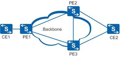
On a network shown in Figure 1, perform the following operations to configure single-segment PWs:

  • Configure the primary and secondary PWs on PE1 and set the PW redundancy mode to Independent or Master/Slave.

  • Configure a primary PW and a bypass PW on PE2 and PE3.

  • (Optional) Configure mPWs between PE1 and PE2, and between PE1 and PE3.

Figure 1 Networking diagram of PW redundancy in the scenario where CEs are asymmetrically connected to PEs (single-segment PWs)

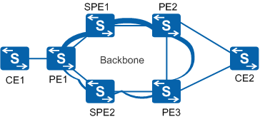
To configure multi-segment PWs on a network shown in Figure 2, configure switching PWs on SPE1 and SPE2 in addition to preceding configurations on single-segment PWs.

Figure 2 Networking diagram of PW redundancy in the scenario where CEs are asymmetrically connected to PEs (multi-segment PWs)

Procedure

  • Configure dynamic primary and secondary PWs.

    Perform the following operations on PE1.

    1. Run system-view

      The system view is displayed.

    2. (Optional) Specify the interface type of the main interface.

      Perform this operation when you need to create a sub-interface.

      1. Run interface interface-type interface-number

        The interface view is displayed.

      2. Run port link-type { hybrid | trunk }

        The interface type is specified.

      3. Run quit

        Exit from the interface view.

    3. Run interface interface-type interface-number [ .subinterface-number ]

      The AC interface view is displayed.

    4. Run mpls l2vc { ip-address | pw-template pw-template-name } * vc-id [ group-id group-id | tunnel-policy policy-name | [ control-word | no-control-word ] | [ raw | tagged ] | mtu mtu-value | ignore-standby-state ] *

      A dynamic primary PW is configured.

    5. (Optional) Run mpls l2vc { ip-address | pw-template pw-template-name } * vc-id [ group-id group-id | tunnel-policy policy-name | [ control-word | no-control-word ] | [ raw | tagged ] | mtu mtu-value | ignore-standby-state ] * secondary

      A dynamic secondary PW is configured.

    6. Run mpls l2vpn redundancy { independent | master }

      The PW redundancy mode is set.

      The Independent mode is recommended to ensure protection switching.

      • When creating a PW, you need to specify the IP address and VC ID of the destination PE. The VC IDs at both ends of a PW must be the same.

      • The default tunnel policy for a dynamic PW uses the LSP tunnel and only one LSP is used for load balancing. To use another tunnel type, specify tunnel-policy policy-name to import the desired tunnel policy.

      • Configure raw or tagged to ensure the same encapsulation type on both ends if the encapsulation type of one end is VLAN and that of the other is Ethernet.
      • The primary and secondary PWs must have the same encapsulation type.

    7. (Optional) Run mpls l2vpn stream-dual-receiving

      An interface is configured to receive packets from both the primary and secondary PWs.

      On a network configured with PW redundancy, you need to configure this command on PEs to which a CE is dual-homed, so that the PEs can receive packets from both the primary and secondary PWs. This can prevent packet loss during a PW revertive switchover.

    8. (Optional) Run mpls l2vpn switchover

      The device is configured to switch service flows from the primary PW to the secondary PW.

      In Master/Slave PW redundancy mode, service flows are transmitted over the primary PW in normal situations. If service flows need to be transmitted over the secondary PW due to reasons such as device upgrade or service re-deployment, use this command to forcibly switch traffic from the primary PW to the secondary PW. After the device is upgraded or services are re-deployed, you can run the undo command to forcibly switch traffic from the secondary PW to the primary PW.

    9. Run quit

      Return to the system view.

  • Configure dynamic primary and bypass PWs.

    Perform the following operations on PE2 and PE3.

    1. Run system-view

      The system view is displayed.

    2. Run interface eth-trunk trunk-id

      An Eth-Trunk is created.

    3. Run port link-type { hybrid | trunk }

      The interface type is specified.

    4. Run quit

      Return to the system view.

    5. Run interface eth-trunk trunk-id.subnumber

      The Eth-Trunk sub-interface view is displayed.

    6. Perform one of the following operations as required.

      • Run dot1q termination vid low-pe-vid

        The single VLAN ID for dot1q encapsulation is set on a sub-interface.

      • Run qinq termination pe-vid pe-vid ce-vid ce-vid1 [ to ce-vid2 ]

        The double VLAN IDs for QinQ encapsulation are set on a sub-interface.

      • Run qinq mapping vid vlan-id1 [ to vlan-id2 ] map-vlan vid vlan-id3

        Single-tagged VLAN mapping is configured on a sub-interface.

      • Run qinq mapping pe-vid vlan-id1 ce-vid vlan-id2 [ to vlan-id3 ] map-vlan vid vlan-id4

        Double-tagged VLAN mapping is configured on a sub-interface.

      • Run qinq stacking vid vlan-id1 [ to vlan-id2 ] pe-vid vlan-id3

        VLAN stacking is configured on a sub-interface.

    7. Run mpls l2vc { ip-address | pw-template pw-template-name } * vc-id [ group-id group-id | tunnel-policy policy-name | [ control-word | no-control-word ] | [ raw | tagged ] | mtu mtu-value | ignore-standby-state ] *

      A dynamic primary PW is configured.

    8. Run mpls l2vc { ip-address | pw-template pw-template-name } * vc-id [ group-id group-id | tunnel-policy policy-name | [ control-word | no-control-word ] | [ raw | tagged ] | mtu mtu-value | ignore-standby-state ] * bypass

      A bypass PW is configured.

      • If tunnel protection is not configured on a public network, configure a bypass PW, an mPW, and BFD to detect public network link faults.

      • If tunnel protection is configured on a public network, you do not need to configure a bypass PW or an mPW.

      • The same encapsulation type must be configured on the two ends of a PW. The primary PW must have the same encapsulation type as the secondary or bypass PW.

      • The control word function must be enabled or disabled on both the bypass PW and the primary PW.

    9. Run quit

      Return to the system view.

  • (Optional) Configure a dynamic switching PW.

    When a multi-segment PW is used, perform the following operations on the SPEs:

    1. Run system-view

      The system view is displayed.

    2. Run mpls switch-l2vc ip-address vc-id between ip-address vc-id encapsulation encapsulation-type [ control-word-transparent ]

      A dynamic switching PW is created.

      With the dynamic switching PW, the remote label is sent from two neighboring endpoints (UPE or SPE) through signaling to the SPE. The control word and virtual circuit connectivity verification (VCCV) capabilities are sent to the SPE through signaling by two UPEs.

      The PW encapsulation type (that is, the parameter following the keyword encapsulation) on the SPE must be the same as the PW encapsulation type on the UPE. Otherwise, the PW cannot go Up.

    3. Run quit

      Return to the system view.

Copyright © Huawei Technologies Co., Ltd.
Next topic >