Example for Configuring Selective QinQ
Networking Requirements
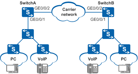
As shown in Figure 1, Internet access users (using PCs) and VoIP users (using VoIP terminals) in an enterprise connect to a carrier network through SwitchA and SwitchB. These users communicate with each other through the carrier network.
The enterprise assigns VLAN 100 to PCs and VLAN 300 to VoIP terminals. Packets from PCs and VoIP terminals need to be transmitted over the carrier network in VLAN 2 and VLAN 3 respectively.
Configuration Roadmap
The configuration roadmap is as follows:
Create VLANs on SwitchA and SwitchB.
Configure link types of interfaces on SwitchA and SwitchB and add the interfaces to VLANs.
Configure selective QinQ on interfaces of SwitchA and SwitchB.
Procedure
- Create VLANs.
# On SwitchA, create VLAN 2 and VLAN 3, that is, VLAN IDs in the outer VLAN tags to be added.
<HUAWEI> system-view
[HUAWEI] sysname SwitchA
[SwitchA] vlan batch 2 3
# On SwitchB, create VLAN 2 and VLAN 3, that is, VLAN IDs in the outer VLAN tags to be added.
<HUAWEI> system-view
[HUAWEI] sysname SwitchB
[SwitchB] vlan batch 2 3
- Configure selective QinQ on interfaces.
# Configure GE0/0/1 on SwitchA.
[SwitchA] interface gigabitethernet 0/0/1
[SwitchA-GigabitEthernet0/0/1] port link-type hybrid
[SwitchA-GigabitEthernet0/0/1] port hybrid untagged vlan 2 3
[SwitchA-GigabitEthernet0/0/1] qinq vlan-translation enable
[SwitchA-GigabitEthernet0/0/1] port vlan-stacking vlan 100 stack-vlan 2
[SwitchA-GigabitEthernet0/0/1] port vlan-stacking vlan 300 stack-vlan 3
[SwitchA-GigabitEthernet0/0/1] quit
# Configure GE0/0/1 on SwitchB.
[SwitchB] interface gigabitethernet 0/0/1
[SwitchB-GigabitEthernet0/0/1] port link-type hybrid
[SwitchB-GigabitEthernet0/0/1] port hybrid untagged vlan 2 3
[SwitchB-GigabitEthernet0/0/1] qinq vlan-translation enable
[SwitchB-GigabitEthernet0/0/1] port vlan-stacking vlan 100 stack-vlan 2
[SwitchB-GigabitEthernet0/0/1] port vlan-stacking vlan 300 stack-vlan 3
[SwitchB-GigabitEthernet0/0/1] quit
- Configure other interfaces.
# Add GE0/0/2 on SwitchA to VLAN 2 and VLAN 3.
[SwitchA] interface gigabitethernet 0/0/2
[SwitchA-GigabitEthernet0/0/2] port link-type trunk
[SwitchA-GigabitEthernet0/0/2] port trunk allow-pass vlan 2 3
[SwitchA-GigabitEthernet0/0/2] quit
# Add GE0/0/2 on SwitchB to VLAN 2 and VLAN 3.
[SwitchB] interface gigabitethernet 0/0/2
[SwitchB-GigabitEthernet0/0/2] port link-type trunk
[SwitchB-GigabitEthernet0/0/2] port trunk allow-pass vlan 2 3
[SwitchB-GigabitEthernet0/0/2] quit
- Verify the configuration.
If the configurations on SwitchA and SwitchB are correct, the following situations occur:
PCs can communicate with each other through the carrier network.
VoIP terminals can communicate with each other through the carrier network.
Configuration Files
SwitchA configuration file
#
sysname SwitchA
#
vlan batch 2 to 3
#
interface GigabitEthernet0/0/1
 port link-type hybrid
 qinq vlan-translation enable
 port hybrid untagged vlan 2 to 3
 port vlan-stacking vlan 100 stack-vlan 2
 port vlan-stacking vlan 300 stack-vlan 3
#
interface GigabitEthernet0/0/2
 port link-type trunk
 port trunk allow-pass vlan 2 to 3
#
return
SwitchB configuration file
#
sysname SwitchB
#
vlan batch 2 to 3
#
interface GigabitEthernet0/0/1
 port link-type hybrid
 qinq vlan-translation enable
 port hybrid untagged vlan 2 to 3
 port vlan-stacking vlan 100 stack-vlan 2
 port vlan-stacking vlan 300 stack-vlan 3
#
interface GigabitEthernet0/0/2
 port link-type trunk
 port trunk allow-pass vlan 2 to 3
#
return