Example for Connecting a Double-Tag VLAN Mapping Sub-Interface to a VLL Network
Networking Requirements
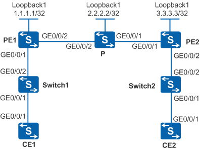
As shown in Figure 1, CE1 and CE2 are connected to PE1 and PE2 respectively through VLANs.
A Martini virtual leased line (VLL) is set up between PE1 and PE2.
Switch1 is connected to CE1 and PE1.
Switch2 is connected to CE2 and PE2.
Selective QinQ needs to be configured on switch interfaces connected to CEs so that the switches can add carrier-specified VLAN tags to packets sent from the CEs.
When Switch1 and Switch2 add different VLAN tags to packets, a double-tag VLAN mapping sub-interface needs to be connect to the VLL network to enable communication between CE1 and CE2.
When a switch is connected to multiple CEs, the switch can add the same outer VLAN tag to packets with different VLAN tags sent from different CEs, thereby conserving VLAN IDs on the public network.

- Only the S5720-EI, S5720-HI, S5730-HI, S5731-H, S5731S-H, S5732-H, S6720-EI, S6720-HI, S6720S-EI, S6730S-H, and S6730-H support this configuration.
- VLAN termination sub-interfaces cannot be created on a VCMP client.
Switch |
Interface |
VLANIF Interface |
IP address |
|---|---|---|---|
PE1 |
GigabitEthernet0/0/1 |
GigabitEthernet0/0/1.1 |
- |
- |
GigabitEthernet0/0/2 |
VLANIF 20 |
10.1.1.1/24 |
- |
Loopback1 |
- |
1.1.1.1/32 |
PE2 |
GigabitEthernet0/0/1 |
VLANIF 30 |
10.2.2.1/24 |
- |
GigabitEthernet0/0/2 |
GigabitEthernet0/0/2.1 |
- |
- |
Loopback1 |
- |
3.3.3.3/32 |
P |
GigabitEthernet0/0/1 |
VLANIF 30 |
10.2.2.2/24 |
- |
GigabitEthernet0/0/2 |
VLANIF 20 |
10.1.1.2/24 |
- |
Loopback1 |
- |
2.2.2.2/32 |
CE1 |
GigabitEthernet0/0/1 |
VLANIF 10 |
10.10.10.1/24 |
CE2 |
GigabitEthernet0/0/1 |
VLANIF 10 |
10.10.10.2/24 |
Configuration Roadmap
The configuration roadmap is as follows:
Configure a routing protocol on PE and P devices of the backbone network to implement network interworking, and enable MPLS.
Use the default tunnel policy to create an LSP for service data transmission.
Enable MPLS L2VPN and create VC connections on PEs.
Create a sub-interface on the interface of PE1 connected to Switch1, configure double-tag VLAN mapping on the sub-interface, and create a VC connection from the sub-interface to the VLL network.
Create a sub-interface on the interface of PE2 connected to Switch2, enable QinQ on the sub-interface, and create a VC connection from the sub-interface to the VLL network.
Configure selective QinQ on the switch interfaces connected to CEs.
Procedure
- Configure VLANs on the CE, PE, and P devices, add interfaces to the VLANs, and assign IP addresses to the corresponding VLANIF interfaces according to Figure 1.
# Configure CE1 to ensure that each packet sent from CE1 to Switch1 carries a single VLAN tag.
<HUAWEI> system-view
[HUAWEI] sysname CE1
[CE1] vlan batch 10
[CE1] interface gigabitethernet 0/0/1
[CE1-GigabitEthernet0/0/1] port link-type trunk
[CE1-GigabitEthernet0/0/1] port trunk allow-pass vlan 10
[CE1-GigabitEthernet0/0/1] quit
[CE1] interface vlanif 10
[CE1-Vlanif10] ip address 10.10.10.1 24
[CE1-Vlanif10] quit
# Configure CE2 to ensure that each packet sent from CE2 to Switch2 carries a single VLAN tag.
<HUAWEI> system-view
[HUAWEI] sysname CE2
[CE2] vlan batch 10
[CE2] interface gigabitethernet 0/0/1
[CE2-GigabitEthernet0/0/1] port link-type trunk
[CE2-GigabitEthernet0/0/1] port trunk allow-pass vlan 10
[CE2-GigabitEthernet0/0/1] quit
[CE2] interface vlanif 10
[CE2-Vlanif10] ip address 10.10.10.2 24
[CE2-Vlanif10] quit
# Configure PE1.
<HUAWEI> system-view
[HUAWEI] sysname PE1
[PE1] vlan batch 20
[PE1] interface gigabitethernet 0/0/2
[PE1-GigabitEthernet0/0/2] port link-type hybrid
[PE1-GigabitEthernet0/0/2] port hybrid pvid vlan 20
[PE1-GigabitEthernet0/0/2] port hybrid tagged vlan 20
[PE1-GigabitEthernet0/0/2] quit
[PE1] interface vlanif 20
[PE1-Vlanif20] ip address 10.1.1.1 24
[PE1-Vlanif20] quit
# Configure P.
<HUAWEI> system-view
[HUAWEI] sysname P
[P] vlan batch 20 30
[P] interface gigabitethernet 0/0/1
[P-GigabitEthernet0/0/1] port link-type hybrid
[P-GigabitEthernet0/0/1] port hybrid pvid vlan 30
[P-GigabitEthernet0/0/1] port hybrid tagged vlan 30
[P-GigabitEthernet0/0/1] quit
[P] interface gigabitethernet 0/0/2
[P-GigabitEthernet0/0/2] port link-type hybrid
[P-GigabitEthernet0/0/2] port hybrid pvid vlan 20
[P-GigabitEthernet0/0/2] port hybrid tagged vlan 20
[P-GigabitEthernet0/0/2] quit
[P] interface vlanif 20
[P-Vlanif20] ip address 10.1.1.2 24
[P-Vlanif20] quit
[P] interface vlanif 30
[P-Vlanif30] ip address 10.2.2.2 24
[P-Vlanif30] quit
# Configure PE2.
<HUAWEI> system-view
[HUAWEI] sysname PE2
[PE2] vlan batch 30
[PE2] interface gigabitethernet 0/0/1
[PE2-GigabitEthernet0/0/1] port link-type hybrid
[PE2-GigabitEthernet0/0/1] port hybrid pvid vlan 30
[PE2-GigabitEthernet0/0/1] port hybrid tagged vlan 30
[PE2-GigabitEthernet0/0/1] quit
[PE2] interface vlanif 30
[PE2-Vlanif30] ip address 10.2.2.1 24
[PE2-Vlanif30] quit
- Configure selective QinQ on switch interfaces and specify the VLANs allowed by the interfaces.
# Configure Switch1.
<HUAWEI> system-view
[HUAWEI] sysname Switch1
[Switch1] vlan 100
[Switch1-vlan100] quit
[Switch1] interface gigabitethernet0/0/2
[Switch1-GigabitEthernet0/0/2] port link-type hybrid
[Switch1-GigabitEthernet0/0/2] port hybrid tagged vlan 100
[Switch1-GigabitEthernet0/0/2] quit
[Switch1] interface gigabitethernet0/0/1
[Switch1-GigabitEthernet0/0/1] port link-type hybrid
[Switch1-GigabitEthernet0/0/1] port hybrid untagged vlan 100
[Switch1-GigabitEthernet0/0/1] qinq vlan-translation enable
[Switch1-GigabitEthernet0/0/1] port vlan-stacking vlan 10 stack-vlan 100
[Switch1-GigabitEthernet0/0/1] quit
# Configure Switch2.
<HUAWEI> system-view
[HUAWEI] sysname Switch2
[Switch2] vlan 200
[Switch2-vlan200] quit
[Switch2] interface gigabitethernet0/0/2
[Switch2-GigabitEthernet0/0/2] port link-type hybrid
[Switch2-GigabitEthernet0/0/2] port hybrid tagged vlan 200
[Switch2-GigabitEthernet0/0/2] quit
[Switch2] interface gigabitethernet0/0/1
[Switch2-GigabitEthernet0/0/1] port link-type hybrid
[Switch2-GigabitEthernet0/0/1] port hybrid untagged vlan 200
[Switch2-GigabitEthernet0/0/1] qinq vlan-translation enable
[Switch2-GigabitEthernet0/0/1] port vlan-stacking vlan 10 stack-vlan 200
[Switch2-GigabitEthernet0/0/1] quit
- Configure an IGP on the MPLS backbone network. OSPF is configured in this example.
Configure PE1, P, and PE2 to advertise 32-bit loopback interface addresses as the LSR IDs.
# Configure PE1.
[PE1] router id 1.1.1.1
[PE1] interface loopback 1
[PE1-LoopBack1] ip address 1.1.1.1 32
[PE1-LoopBack1] quit
[PE1] ospf 1
[PE1-ospf-1] area 0
[PE1-ospf-1-area-0.0.0.0] network 1.1.1.1 0.0.0.0
[PE1-ospf-1-area-0.0.0.0] network 10.1.1.1 0.0.0.255
[PE1-ospf-1-area-0.0.0.0] quit
[PE1-ospf-1] quit
# Configure P.
[P] router id 2.2.2.2
[P] interface loopback 1
[P-LoopBack1] ip address 2.2.2.2 32
[P-LoopBack1] quit
[P] ospf 1
[P-ospf-1] area 0
[P-ospf-1-area-0.0.0.0] network 2.2.2.2 0.0.0.0
[P-ospf-1-area-0.0.0.0] network 10.1.1.2 0.0.0.255
[P-ospf-1-area-0.0.0.0] network 10.2.2.2 0.0.0.255
[P-ospf-1-area-0.0.0.0] quit
[P-ospf-1] quit
# Configure PE2.
[PE2] router id 3.3.3.3
[PE2] interface loopback 1
[PE2-LoopBack1] ip address 3.3.3.3 32
[PE2-LoopBack1] quit
[PE2] ospf 1
[PE2-ospf-1] area 0
[PE2-ospf-1-area-0.0.0.0] network 3.3.3.3 0.0.0.0
[PE2-ospf-1-area-0.0.0.0] network 10.2.2.1 0.0.0.255
[PE2-ospf-1-area-0.0.0.0] quit
[PE2-ospf-1] quit
# After the configuration is complete, PE1, P, and PE2 can establish OSPF neighbor relationships. Run the display ospf peer command to verify that the OSPF neighbor relationship status is Full. Run the display ip routing-table command to verify that the PEs learn the route to the Loopback1 interface of each other. The following is the display on PE1:
[PE1] display ospf peer

         OSPF Process 1 with Router ID 1.1.1.1
                 Neighbors

 Area 0.0.0.0 interface 10.1.1.1(Vlanif20)'s neighbors
 Router ID: 2.2.2.2      Address: 10.1.1.2
   State: Full  Mode:Nbr is  Master  Priority: 1
   DR: 10.1.1.2  BDR: 10.1.1.1  MTU: 0
   Dead timer due in 34  sec
   Retrans timer interval: 5
   Neighbor is up for 00:01:16
   Authentication Sequence: [ 0 ]
[PE1] display ip routing-table Route Flags: R - relay, D - download to fib, T - to vpn-instance ------------------------------------------------------------------------------ Routing Tables: Public Destinations : 8 Routes : 8 Destination/Mask Proto Pre Cost Flags NextHop Interface 1.1.1.1/32 Direct 0 0 D 127.0.0.1 LoopBack1 2.2.2.2/32 OSPF 10 1 D 10.1.1.2 Vlanif20 3.3.3.3/32 OSPF 10 2 D 10.1.1.2 Vlanif20 10.1.1.0/24 Direct 0 0 D 10.1.1.1 Vlanif20 10.1.1.1/32 Direct 0 0 D 127.0.0.1 Vlanif20 10.2.2.0/24 OSPF 10 2 D 10.1.1.2 Vlanif20 127.0.0.0/8 Direct 0 0 D 127.0.0.1 InLoopBack0 127.0.0.1/32 Direct 0 0 D 127.0.0.1 InLoopBack0 - Enable basic MPLS functions and MPLS LDP on the MPLS backbone network.
# Configure PE1.
[PE1] mpls lsr-id 1.1.1.1
[PE1] mpls
[PE1-mpls] quit
[PE1] mpls ldp
[PE1-mpls-ldp] quit
[PE1] interface vlanif 20
[PE1-Vlanif20] mpls
[PE1-Vlanif20] mpls ldp
[PE1-Vlanif20] quit
# Configure P.
[P] mpls lsr-id 2.2.2.2
[P] mpls
[P-mpls] quit
[P] mpls ldp
[P-mpls-ldp] quit
[P] interface vlanif 20
[P-Vlanif20] mpls
[P-Vlanif20] mpls ldp
[P-Vlanif20] quit
[P] interface vlanif 30
[P-Vlanif30] mpls
[P-Vlanif30] mpls ldp
[P-Vlanif30] quit
# Configure PE2.
[PE2] mpls lsr-id 3.3.3.3
[PE2] mpls
[PE2-mpls] quit
[PE2] mpls ldp
[PE2-mpls-ldp] quit
[PE2] interface vlanif 30
[PE2-Vlanif30] mpls
[PE2-Vlanif30] mpls ldp
[PE2-Vlanif30] quit
- Create remote LDP sessions between PEs.
# Configure PE1.
[PE1] mpls ldp remote-peer 3.3.3.3
[PE1-mpls-ldp-remote-3.3.3.3] remote-ip 3.3.3.3
[PE1-mpls-ldp-remote-3.3.3.3] quit
# Configure PE2.
[PE2] mpls ldp remote-peer 1.1.1.1
[PE2-mpls-ldp-remote-1.1.1.1] remote-ip 1.1.1.1
[PE2-mpls-ldp-remote-1.1.1.1] quit
After the configuration is complete, run the display mpls ldp session command on PE1 to view information about LDP sessions. The following output indicates that an LDP session has been set up between PE1 and PE2.
[PE1] display mpls ldp session
 LDP Session(s) in Public Network
 Codes: LAM(Label Advertisement Mode), SsnAge Unit(DDDD:HH:MM)
 A '*' before a session means the session is being deleted.
 ------------------------------------------------------------------------------
 PeerID            Status      LAM  SsnRole  SsnAge      KASent/Rcv
 ------------------------------------------------------------------------------
 2.2.2.2:0          Operational DU Passive  0000:15:29   3717/3717
 3.3.3.3:0          Operational DU Passive  0000:00:00   2/2
 ------------------------------------------------------------------------------
 TOTAL: 2 session(s) Found.
- Enable MPLS L2VPN on PEs and create VC connections.
# On PE1, create a VC connection on GigabitEthernet0/0/1.1 connected to CE1.
[PE1] mpls l2vpn
[PE1-l2vpn] quit
[PE1] vcmp role silent
[PE1] interface gigabitethernet0/0/1
[PE1-GigabitEthernet0/0/1] port link-type hybrid
[PE1-GigabitEthernet0/0/1] quit
[PE1] interface gigabitethernet0/0/1.1
[PE1-GigabitEthernet0/0/1.1] qinq mapping pe-vid 100 ce-vid 10 map-vlan vid 200
[PE1-GigabitEthernet0/0/1.1] mpls l2vc 3.3.3.3 101
[PE1-GigabitEthernet0/0/1.1] quit
# On PE2, create a VC connection on GigabitEthernet0/0/2.1 connected to Switch2.
[PE2] mpls l2vpn
[PE2-l2vpn] quit
[PE2] vcmp role silent
[PE2] interface gigabitethernet0/0/2
[PE2-GigabitEthernet0/0/2] port link-type hybrid
[PE2-GigabitEthernet0/0/2] quit
[PE2] interface gigabitethernet0/0/2.1
[PE2-GigabitEthernet0/0/2.1] qinq termination pe-vid 200 ce-vid 10
[PE2-GigabitEthernet0/0/2.1] mpls l2vc 1.1.1.1 101
[PE2-GigabitEthernet0/0/2.1] quit
- Verify the configuration.
Check the L2VPN connections on PEs. You can see that an L2VC connection has been set up and is in Up state.
The following command on PE1 is used as an example:
[PE1] display mpls l2vc interface gigabitethernet0/0/1.1
 *client interface       : GigabitEthernet0/0/1.1 is up
  Administrator PW       : no
  session state          : up
  AC status              : up
  Ignore AC state        : disable
  VC state               : up
  Label state            : 0
  Token state            : 0
  VC ID                  : 101
  VC type                : VLAN
  destination            : 3.3.3.3
  local group ID         : 0            remote group ID      : 0
  local VC label         : 23552        remote VC label      : 23552
  local AC OAM State     : up
  local PSN OAM State    : up
  local forwarding state : forwarding
  local status code      : 0x0
  remote AC OAM state    : up
  remote PSN OAM state   : up
  remote forwarding state: forwarding
  remote status code     : 0x0
  ignore standby state   : no
  BFD for PW             : unavailable
  VCCV State             : up
  manual fault           : not set
  active state           : active
  forwarding entry       : exist
  link state             : up
  local VC MTU           : 1500         remote VC MTU        : 1500
  local VCCV             : alert ttl lsp-ping bfd
  remote VCCV            : alert ttl lsp-ping bfd
  local control word     : disable      remote control word  : disable
  tunnel policy name     : --
  PW template name       : --
  primary or secondary   : primary
  load balance type      : flow
  Access-port            : false
  Switchover Flag        : false
  VC tunnel/token info   : 1 tunnels/tokens
    NO.0  TNL type       : lsp   , TNL ID : 0x10031
    Backup TNL type      : lsp   , TNL ID : 0x0
  create time            : 1 days, 22 hours, 15 minutes, 9 seconds
  up time                : 0 days, 22 hours, 54 minutes, 57 seconds
  last change time       : 0 days, 22 hours, 54 minutes, 57 seconds
  VC last up time        : 2010/10/09 19:26:37
  VC total up time       : 1 days, 20 hours, 42 minutes, 30 seconds
  CKey                   : 8
  NKey                   : 3
  PW redundancy mode     : --
  AdminPw interface      : --
  AdminPw link state     : --
  Diffserv Mode          : uniform
  Service Class          : --
  Color                  : --
  DomainId               : --
  Domain Name            : --
CE1 and CE2 can ping each other.
The following output on CE1 is used as an example:
[CE1] ping 10.10.10.2
 PING 10.10.10.2: 56  data bytes, press CTRL_C to break
    Reply from 10.10.10.2: bytes=56 Sequence=1 ttl=255 time=6 ms
    Reply from 10.10.10.2: bytes=56 Sequence=2 ttl=255 time=5 ms
    Reply from 10.10.10.2: bytes=56 Sequence=3 ttl=255 time=5 ms
    Reply from 10.10.10.2: bytes=56 Sequence=4 ttl=255 time=13 ms
    Reply from 10.10.10.2: bytes=56 Sequence=5 ttl=255 time=5 ms

  --- 10.10.10.2 ping statistics ---
    5 packet(s) transmitted
    5 packet(s) received
    0.00% packet loss
    round-trip min/avg/max = 5/6/13 ms
Configuration Files
CE1 configuration file
#
sysname CE1
#
vlan batch 10
#
interface Vlanif10
 ip address 10.10.10.1 255.255.255.0
#
interface GigabitEthernet0/0/1
 port link-type trunk
 port trunk allow-pass vlan 10
#
return
Switch1 configuration file
#
sysname Switch1
#
vlan batch 100
#
interface GigabitEthernet0/0/1
 port link-type hybrid
 qinq vlan-translation enable
 port hybrid untagged vlan 100
 port vlan-stacking vlan 10 stack-vlan 100
#
interface GigabitEthernet0/0/2
 port link-type hybrid
 port hybrid tagged vlan 100
#
return
PE1 configuration file
#
sysname PE1
#
router id 1.1.1.1
#
vcmp role silent
#
vlan batch 20
#
mpls lsr-id 1.1.1.1
mpls
#
mpls l2vpn
#
mpls ldp
#
mpls ldp remote-peer 3.3.3.3
 remote-ip 3.3.3.3
#
interface Vlanif20
 ip address 10.1.1.1 255.255.255.0
 mpls
 mpls ldp
#
interface GigabitEthernet0/0/1  port link-type hybrid
#
interface GigabitEthernet0/0/1.1
 qinq mapping pe-vid 100 ce-vid 10 map-vlan vid 200
 mpls l2vc 3.3.3.3 101
#
interface GigabitEthernet0/0/2
 port link-type hybrid
 port hybrid pvid vlan 20
 port hybrid tagged vlan 20
#
interface LoopBack1
 ip address 1.1.1.1 255.255.255.255
#
ospf 1
 area 0.0.0.0
  network 1.1.1.1 0.0.0.0
  network 10.1.1.0 0.0.0.255
#
return
P configuration file
#
sysname P
#
router id 2.2.2.2
#
vlan batch 20 30
#
mpls lsr-id 2.2.2.2
mpls
#
mpls ldp
#
interface Vlanif20
 ip address 10.1.1.2 255.255.255.0
 mpls
 mpls ldp
#
interface Vlanif30
 ip address 10.2.2.2 255.255.255.0
 mpls
 mpls ldp
#
interface GigabitEthernet0/0/1
 port link-type hybrid
 port hybrid pvid vlan 30
 port hybrid tagged vlan 30
#
interface GigabitEthernet0/0/2
 port link-type hybrid
 port hybrid pvid vlan 20
 port hybrid tagged vlan 20
#
interface LoopBack1
 ip address 2.2.2.2 255.255.255.255
#
ospf 1
 area 0.0.0.0
  network 2.2.2.2 0.0.0.0
  network 10.1.1.0 0.0.0.255
  network 10.2.2.0 0.0.0.255
#
return
PE2 configuration file
#
sysname PE2
#
router id 3.3.3.3
#
vcmp role silent
#
vlan batch 30
#
mpls lsr-id 3.3.3.3
mpls
#
mpls l2vpn
#
mpls ldp
#
mpls ldp remote-peer 1.1.1.1
 remote-ip 1.1.1.1
#
interface Vlanif30
 ip address 10.2.2.1 255.255.255.0
 mpls
 mpls ldp
#
interface GigabitEthernet0/0/1
 port link-type hybrid
 port hybrid pvid vlan 30
 port hybrid tagged vlan 30
#
interface GigabitEthernet0/0/2  port link-type hybrid
#
interface GigabitEthernet0/0/2.1
 qinq termination pe-vid 200 ce-vid 10
 mpls l2vc 1.1.1.1 101
#
interface LoopBack1
 ip address 3.3.3.3 255.255.255.255
#
ospf 1
 area 0.0.0.0
  network 3.3.3.3 0.0.0.0
  network 10.2.2.0 0.0.0.255
#
return
Switch2 configuration file
#
sysname Switch2
#
vlan batch 200
#
interface GigabitEthernet0/0/1
 port link-type hybrid
 qinq vlan-translation enable
 port hybrid untagged vlan 200
 port vlan-stacking vlan 10 stack-vlan 200
#
interface GigabitEthernet0/0/2
 port link-type hybrid
 port hybrid tagged vlan 200
#
return
CE2 configuration file
#
sysname CE2
#
vlan batch 10
#
interface Vlanif10
 ip address 10.10.10.2 255.255.255.0
#
interface GigabitEthernet0/0/1
 port link-type trunk
 port trunk allow-pass vlan 10
#
return