Example for Connecting a Double-Tag VLAN Mapping Sub-interface to a VPLS Network
Networking Requirements
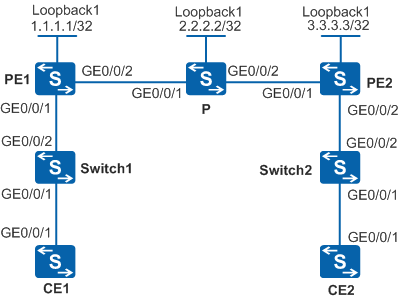
As shown in Figure 1, VPLS is enabled on PE1 and PE2. CE1 connects to PE1 through Switch1, and CE2 connects to PE2 through Switch2. CE1 and CE2 are on the same VPLS network. To enable communication between CE1 and CE2, LDP is used as the VPLS signaling protocol to establish PWs and VPLS is configured.
Selective QinQ needs to be configured on the switch interfaces connected to CEs so that Switch1 and Switch2 add the carrier-specified VLAN tags to the packets sent from CEs.
When Switch1 and Switch2 allow different VLAN tags, a double-tag VLAN mapping sub-interface on a PE needs to connect to the VPLS network to enable communication between CE1 and CE2.
When a switch is connected to multiple CEs, the switch can add the same outer VLAN tag to packets with different VLAN tags from different CEs, thereby conserving VLAN IDs on the public network.

- Only the S5720-EI, S5720-HI, S5730-HI, S5731-H, S5731S-H, S5732-H, S6720-EI, S6720-HI, S6720S-EI, S6730S-H, and S6730-H support this configuration.
- VLAN termination sub-interfaces cannot be created on a VCMP client.
- Only the S5720-EI, S5720-HI, S5730-HI, S5731-H, S5731S-H, S5732-H, S6720-EI, S6720-HI, S6720S-EI, S6730S-H, and S6730-H support this configuration.
- VLAN termination sub-interfaces cannot be created on a VCMP client.
Switch |
Interface |
VLANIF Interface |
IP Address |
|---|---|---|---|
PE1 |
GigabitEthernet0/0/1 |
GigabitEthernet0/0/1.1 |
- |
- |
GigabitEthernet0/0/2 |
VLANIF 20 |
4.4.4.4/24 |
- |
Loopback1 |
- |
1.1.1.1/32 |
PE2 |
GigabitEthernet0/0/1 |
VLANIF 30 |
5.5.5.5/24 |
- |
GigabitEthernet0/0/2 |
GigabitEthernet0/0/2.1 |
- |
- |
Loopback1 |
- |
3.3.3.3/32 |
P |
GigabitEthernet0/0/1 |
VLANIF 20 |
4.4.4.5/24 |
- |
GigabitEthernet0/0/2 |
VLANIF 30 |
5.5.5.4/24 |
- |
Loopback1 |
- |
2.2.2.2/32 |
CE1 |
GigabitEthernet0/0/1 |
VLANIF 10 |
10.1.1.1/24 |
CE2 |
GigabitEthernet0/0/1 |
VLANIF 10 |
10.1.1.2/24 |
Configuration Roadmap
The configuration roadmap is as follows:
Configure a routing protocol on the backbone network to implement network interworking.
Configure selective QinQ on the switch interfaces connected to CEs.
Set up a remote LDP session between PEs.
Establish tunnels between PEs for service data transmission.
Enable MPLS L2VPN on PEs.
Create a VSI on the PEs and specify LDP as the signaling protocol.
Configure double-tag VLAN mapping on the sub-interface connected to Switch1 on PE1 and bind the sub-interface to the VSI to connect it to the VPLS network.
Configure a QinQ sub-interface on the interface connected to Switch2 on PE2 and bind the sub-interface to the VSI to connect it to the VPLS network.
Procedure
- Create VLANs on the devices, add interfaces to the VLANs, and assign IP addresses to VLANIF interfaces according to Figure 1.
# Configure CE1.
<HUAWEI> system-view
[HUAWEI] sysname CE1
[CE1] vlan batch 10
[CE1] interface gigabitethernet 0/0/1
[CE1-GigabitEthernet0/0/1] port link-type trunk
[CE1-GigabitEthernet0/0/1] port trunk allow-pass vlan 10
[CE1-GigabitEthernet0/0/1] quit
[CE1] interface vlanif 10
[CE1-Vlanif10] ip address 10.1.1.1 24
[CE1-Vlanif10] quit
# Configure CE2.
<HUAWEI> system-view
[HUAWEI] sysname CE2
[CE2] vlan batch 10
[CE2] interface gigabitethernet 0/0/1
[CE2-GigabitEthernet0/0/1] port link-type trunk
[CE2-GigabitEthernet0/0/1] port trunk allow-pass vlan 10
[CE2-GigabitEthernet0/0/1] quit
[CE2] interface vlanif 10
[CE2-Vlanif10] ip address 10.1.1.2 24
[CE2-Vlanif10] quit
# Configure PE1.
<HUAWEI> system-view
[HUAWEI] sysname PE1
[PE1] vlan batch 20
[PE1] interface gigabitethernet 0/0/2
[PE1-GigabitEthernet0/0/2] port link-type hybrid
[PE1-GigabitEthernet0/0/2] port hybrid pvid vlan 20
[PE1-GigabitEthernet0/0/2] port hybrid tagged vlan 20
[PE1-GigabitEthernet0/0/2] quit
[PE1] interface vlanif 20
[PE1-Vlanif20] ip address 4.4.4.4 24
[PE1-Vlanif20] quit
# Configure P.
<HUAWEI> system-view
[HUAWEI] sysname P
[P] vlan batch 20 30
[P] interface gigabitethernet 0/0/1
[P-GigabitEthernet0/0/1] port link-type hybrid
[P-GigabitEthernet0/0/1] port hybrid pvid vlan 20
[P-GigabitEthernet0/0/1] port hybrid tagged vlan 20
[P-GigabitEthernet0/0/1] quit
[P] interface gigabitethernet 0/0/2
[P-GigabitEthernet0/0/2] port link-type hybrid
[P-GigabitEthernet0/0/2] port hybrid pvid vlan 30
[P-GigabitEthernet0/0/2] port hybrid tagged vlan 30
[P-GigabitEthernet0/0/2] quit
[P] interface vlanif 20
[P-Vlanif20] ip address 4.4.4.5 24
[P-Vlanif20] quit
[P] interface vlanif 30
[P-Vlanif30] ip address 5.5.5.4 24
[P-Vlanif30] quit
# Configure PE2.
<HUAWEI> system-view
[HUAWEI] sysname PE2
[PE2] vlan batch 30
[PE2] interface gigabitethernet 0/0/1
[PE2-GigabitEthernet0/0/1] port link-type hybrid
[PE2-GigabitEthernet0/0/1] port hybrid pvid vlan 30
[PE2-GigabitEthernet0/0/1] port hybrid tagged vlan 30
[PE2-GigabitEthernet0/0/1] quit
[PE2] interface vlanif 30
[PE2-Vlanif30] ip address 5.5.5.5 24
[PE2-Vlanif30] quit
- Configure selective QinQ on switch interfaces and specify the VLANs allowed by the interfaces.
# Configure Switch1.
<HUAWEI> system-view
[HUAWEI] sysname Switch1
[Switch1] vlan 100
[Switch1-vlan100] quit
[Switch1] interface gigabitethernet0/0/2
[Switch1-GigabitEthernet0/0/2] port link-type hybrid
[Switch1-GigabitEthernet0/0/2] port hybrid tagged vlan 100
[Switch1-GigabitEthernet0/0/2] quit
[Switch1] interface gigabitethernet0/0/1
[Switch1-GigabitEthernet0/0/1] port link-type hybrid
[Switch1-GigabitEthernet0/0/1] qinq vlan-translation enable
[Switch1-GigabitEthernet0/0/1] port hybrid untagged vlan 100
[Switch1-GigabitEthernet0/0/1] port vlan-stacking vlan 10 stack-vlan 100
[Switch1-GigabitEthernet0/0/1] quit
# Configure Switch2.
<HUAWEI> system-view
[HUAWEI] sysname Switch2
[Switch2] vlan 200
[Switch2-vlan200] quit
[Switch2] interface gigabitethernet0/0/2
[Switch2-GigabitEthernet0/0/2] port link-type hybrid
[Switch2-GigabitEthernet0/0/2] port hybrid tagged vlan 200
[Switch2-GigabitEthernet0/0/2] quit
[Switch2] interface gigabitethernet0/0/1
[Switch2-GigabitEthernet0/0/1] port link-type hybrid
[Switch2-GigabitEthernet0/0/1] qinq vlan-translation enable
[Switch2-GigabitEthernet0/0/1] port hybrid untagged vlan 200
[Switch2-GigabitEthernet0/0/1] port vlan-stacking vlan 10 stack-vlan 200
[Switch2-GigabitEthernet0/0/1] quit
- Configure an IGP protocol. OSPF is used in this example.
Configure PE1, P, and PE2 to advertise 32-bit loopback interface addresses as the LSR IDs.
# Configure PE1.
[PE1] router id 1.1.1.1
[PE1] interface loopback 1
[PE1-LoopBack1] ip address 1.1.1.1 32
[PE1-LoopBack1] quit
[PE1] ospf 1
[PE1-ospf-1] area 0
[PE1-ospf-1-area-0.0.0.0] network 1.1.1.1 0.0.0.0
[PE1-ospf-1-area-0.0.0.0] network 4.4.4.4 0.0.0.255
[PE1-ospf-1-area-0.0.0.0] quit
[PE1-ospf-1] quit
# Configure P.
[P] router id 2.2.2.2
[P] interface loopback 1
[P-LoopBack1] ip address 2.2.2.2 32
[P-LoopBack1] quit
[P] ospf 1
[P-ospf-1] area 0
[P-ospf-1-area-0.0.0.0] network 2.2.2.2 0.0.0.0
[P-ospf-1-area-0.0.0.0] network 4.4.4.5 0.0.0.255
[P-ospf-1-area-0.0.0.0] network 5.5.5.4 0.0.0.255
[P-ospf-1-area-0.0.0.0] quit
[P-ospf-1] quit
# Configure PE2.
[PE2] router id 3.3.3.3
[PE2] interface loopback 1
[PE2-LoopBack1] ip address 3.3.3.3 32
[PE2-LoopBack1] quit
[PE2] ospf 1
[PE2-ospf-1] area 0
[PE2-ospf-1-area-0.0.0.0] network 3.3.3.3 0.0.0.0
[PE2-ospf-1-area-0.0.0.0] network 5.5.5.5 0.0.0.255
[PE2-ospf-1-area-0.0.0.0] quit
[PE2-ospf-1] quit
After the configuration is complete, run the display ip routing-table command on PE1, P, and PE2. You can view the routes that PE1, P, and PE2 have learned from each other. The following is the display on PE1:
[PE1] display ip routing-table Route Flags: R - relay, D - download to fib, T - to vpn-instance ------------------------------------------------------------------------------ Routing Tables: Public Destinations : 8 Routes : 8 Destination/Mask Proto Pre Cost Flags NextHop Interface 1.1.1.1/32 Direct 0 0 D 127.0.0.1 LoopBack1 2.2.2.2/32 OSPF 10 1 D 4.4.4.5 Vlanif20 3.3.3.3/32 OSPF 10 2 D 4.4.4.5 Vlanif20 4.4.4.0/24 Direct 0 0 D 4.4.4.4 Vlanif20 4.4.4.4/32 Direct 0 0 D 127.0.0.1 Vlanif20 5.5.5.0/24 OSPF 10 2 D 4.4.4.5 Vlanif20 127.0.0.0/8 Direct 0 0 D 127.0.0.1 InLoopBack0 127.0.0.1/32 Direct 0 0 D 127.0.0.1 InLoopBack0 - Enable basic MPLS functions and MPLS LDP.
# Configure PE1.
[PE1] mpls lsr-id 1.1.1.1
[PE1] mpls
[PE1-mpls] quit
[PE1] mpls ldp
[PE1-mpls-ldp] quit
[PE1] interface vlanif 20
[PE1-Vlanif20] mpls
[PE1-Vlanif20] mpls ldp
[PE1-Vlanif20] quit
# Configure P.
[P] mpls lsr-id 2.2.2.2
[P] mpls
[P-mpls] quit
[P] mpls ldp
[P-mpls-ldp] quit
[P] interface vlanif 20
[P-Vlanif20] mpls
[P-Vlanif20] mpls ldp
[P-Vlanif20] quit
[P] interface vlanif 30
[P-Vlanif30] mpls
[P-Vlanif30] mpls ldp
[P-Vlanif30] quit
# Configure PE2.
[PE2] mpls lsr-id 3.3.3.3
[PE2] mpls
[PE2-mpls] quit
[PE2] mpls ldp
[PE2-mpls-ldp] quit
[PE2] interface vlanif 30
[PE2-Vlanif30] mpls
[PE2-Vlanif30] mpls ldp
[PE2-Vlanif30] quit
After the configuration is complete, run the display mpls ldp session command on PE1, P, and PE2. You can see that the peer relationships are set up between PE1 and P, and between P and PE2. The status of the peer relationship is Operational. Run the display mpls ldp command to view the MPLS LDP configuration. The following is the display on PE1:
[PE1] display mpls ldp session
 LDP Session(s) in Public Network
 Codes: LAM(Label Advertisement Mode), SsnAge Unit(DDDD:HH:MM)
 A '*' before a session means the session is being deleted.
 ------------------------------------------------------------------------------
 PeerID            Status      LAM  SsnRole  SsnAge      KASent/Rcv
 ------------------------------------------------------------------------------
 2.2.2.2:0          Operational DU Passive  0000:15:29   3717/3717
 ------------------------------------------------------------------------------
 TOTAL: 1 session(s) Found.
- Set up a remote LDP session between PEs.
# Configure PE1.
[PE1] mpls ldp remote-peer 3.3.3.3
[PE1-mpls-ldp-remote-3.3.3.3] remote-ip 3.3.3.3
[PE1-mpls-ldp-remote-3.3.3.3] quit
# Configure PE2.
[PE2] mpls ldp remote-peer 1.1.1.1
[PE2-mpls-ldp-remote-1.1.1.1] remote-ip 1.1.1.1
[PE2-mpls-ldp-remote-1.1.1.1] quit
After the configuration is complete, run the display mpls ldp session command on PE1 or PE2 to check that the status of the peer relationship between PE1 and PE2 is Operational, indicating that the peer relationship is set up. The following output is shown on PE1.
[PE1] display mpls ldp session
 LDP Session(s) in Public Network
 Codes: LAM(Label Advertisement Mode), SsnAge Unit(DDDD:HH:MM)
 A '*' before a session means the session is being deleted.
 ------------------------------------------------------------------------------
 PeerID            Status      LAM  SsnRole  SsnAge      KASent/Rcv
 ------------------------------------------------------------------------------
 2.2.2.2:0          Operational DU Passive  0000:15:29   3717/3717
 3.3.3.3:0          Operational DU Passive  0000:00:00   2/2
 ------------------------------------------------------------------------------
 TOTAL: 2 session(s) Found.
- Enable MPLS L2VPN on the PEs.
# Configure PE1.
[PE1] mpls l2vpn
[PE1-l2vpn] quit
# Configure PE2.
[PE2] mpls l2vpn
[PE2-l2vpn] quit
- Configure a VSI on the PEs.
# Configure PE1.
[PE1] vsi a2 static
[PE1-vsi-a2] pwsignal ldp
[PE1-vsi-a2-ldp] vsi-id 2
[PE1-vsi-a2-ldp] peer 3.3.3.3
[PE1-vsi-a2-ldp] quit
[PE1-vsi-a2] quit
# Configure PE2.
[PE2] vsi a2 static
[PE2-vsi-a2] pwsignal ldp
[PE2-vsi-a2-ldp] vsi-id 2
[PE2-vsi-a2-ldp] peer 1.1.1.1
[PE2-vsi-a2-ldp] quit
[PE2-vsi-a2] quit
- Bind sub-interfaces to the VSI on PEs.
# Configure PE1.
[PE1] vcmp role silent
[PE1] interface gigabitethernet0/0/1
[PE1-GigabitEthernet0/0/1] port link-type hybrid
[PE1-GigabitEthernet0/0/1] quit
[PE1] interface gigabitethernet0/0/1.1
[PE1-GigabitEthernet0/0/1.1] qinq mapping pe-vid 100 ce-vid 10 map-vlan vid 200
[PE1-GigabitEthernet0/0/1.1] l2 binding vsi a2
[PE1-GigabitEthernet0/0/1.1] quit
# Configure PE2.
[PE2] vcmp role silent
[PE2] interface gigabitethernet0/0/2
[PE2-GigabitEthernet0/0/2] port link-type hybrid
[PE2-GigabitEthernet0/0/2] quit
[PE2] interface gigabitethernet0/0/2.1
[PE2-GigabitEthernet0/0/2.1] qinq termination pe-vid 200 ce-vid 10
[PE2-GigabitEthernet0/0/2.1] l2 binding vsi a2
[PE2-GigabitEthernet0/0/2.1] quit
- Verify the configuration.
After the configuration is complete, run the display vsi name a2 verbose command on PE1. The following output indicates that the VSI a2 sets up a PW to PE2 and the VSI status is Up.
[PE1] display vsi name a2 verbose

 ***VSI Name               : a2
    Administrator VSI      : no
    Isolate Spoken         : disable
    VSI Index              : 0
    PW Signaling           : ldp
    Member Discovery Style : static
    PW MAC Learn Style     : unqualify
    Encapsulation Type     : vlan
    MTU                    : 1500
    Diffserv Mode          : uniform
    Mpls Exp               : --
    DomainId               : 255
    Domain Name            :
    Ignore AcState         : disable
    P2P VSI                : disable
    Create Time            : 0 days, 0 hours, 5 minutes, 1 seconds
    VSI State              : up

    VSI ID                 : 2
   *Peer Router ID         : 3.3.3.3
    Negotiation-vc-id      : 2
    primary or secondary   : primary
    ignore-standby-state   : no
    VC Label               : 23552
    Peer Type              : dynamic
    Session                : up
    Tunnel ID              : 0x22
    Broadcast Tunnel ID    : 0x22
    Broad BackupTunnel ID  : 0x0
    CKey                   : 2
    NKey                   : 1
    Stp Enable             : 0
    PwIndex                : 0
    Control Word           : disable

    Interface Name         : gigabitethernet0/0/1.1
    State                  : up
    Access Port            : false
    Last Up Time           : 2010/12/30 11:31:18
    Total Up Time          : 0 days, 0 hours, 1 minutes, 35 seconds

  **PW Information:

   *Peer Ip Address        : 3.3.3.3
    PW State               : up
    Local VC Label         : 23552
    Remote VC Label        : 23552
    Remote Control Word    : disable
    PW Type                : label
    Local  VCCV            : alert lsp-ping bfd
    Remote VCCV            : alert lsp-ping bfd
    Tunnel ID              : 0x22
    Broadcast Tunnel ID    : 0x22
    Broad BackupTunnel ID  : 0x0
    Ckey                   : 0x2
    Nkey                   : 0x1
    Main PW Token          : 0x22
    Slave PW Token         : 0x0
    Tnl Type               : LSP
    OutInterface           : Vlanif20
    Backup OutInterface    :
    Stp Enable             : 0
    PW Last Up Time        : 2010/12/30 11:32:03
    PW Total Up Time       : 0 days, 0 hours, 0 minutes, 50 seconds
CE1 (10.1.1.1) can ping CE2 (10.1.1.2) successfully.
<CE1> ping 10.1.1.2
  PING 10.1.1.2: 56  data bytes, press CTRL_C to break
    Reply from 10.1.1.2: bytes=56 Sequence=1 ttl=255 time=90 ms
    Reply from 10.1.1.2: bytes=56 Sequence=2 ttl=255 time=77 ms
    Reply from 10.1.1.2: bytes=56 Sequence=3 ttl=255 time=34 ms
    Reply from 10.1.1.2: bytes=56 Sequence=4 ttl=255 time=46 ms
    Reply from 10.1.1.2: bytes=56 Sequence=5 ttl=255 time=94 ms

  --- 10.1.1.2 ping statistics ---
    5 packet(s) transmitted
    5 packet(s) received
    0.00% packet loss
    round-trip min/avg/max = 34/68/94 ms
Configuration Files
CE1 configuration file
#
sysname CE1
#
vlan batch 10
#
interface Vlanif10
 ip address 10.1.1.1 255.255.255.0
#
interface GigabitEthernet0/0/1
 port link-type trunk
 port trunk allow-pass vlan 10
#
return
CE2 configuration file
#
sysname CE2
#
vlan batch 10
#
interface Vlanif10
 ip address 10.1.1.2 255.255.255.0
#
interface GigabitEthernet0/0/1
 port link-type trunk
 port trunk allow-pass vlan 10
#
return
Switch1 configuration file
#
sysname Switch1
#
vlan batch 100
#
interface GigabitEthernet0/0/1
 port link-type hybrid
 qinq vlan-translation enable
 port hybrid untagged vlan 100
 port vlan-stacking vlan 10 stack-vlan 100
#
interface GigabitEthernet0/0/2
 port link-type hybrid
 port hybrid tagged vlan 100
#
return
Switch2 configuration file
#
sysname Switch2
#
vlan batch 200
#
interface GigabitEthernet0/0/1
 port link-type hybrid
 qinq vlan-translation enable
 port hybrid untagged vlan 200
 port vlan-stacking vlan 10 stack-vlan 200
#
interface GigabitEthernet0/0/2
 port link-type hybrid
 port hybrid tagged vlan 200
#
return
PE1 configuration file
#
sysname PE1
#
router id 1.1.1.1
#
vcmp role silent
#
vlan batch 20
#
mpls lsr-id 1.1.1.1
mpls
#
mpls l2vpn
#
vsi a2 static
 pwsignal ldp
  vsi-id 2
  peer 3.3.3.3
#
mpls ldp
#
mpls ldp remote-peer 3.3.3.3
 remote-ip 3.3.3.3
#
interface Vlanif20
 ip address 4.4.4.4 255.255.255.0
 mpls
 mpls ldp
#
interface GigabitEthernet0/0/1  port link-type hybrid
#
interface GigabitEthernet0/0/1.1
 qinq mapping pe-vid 100 ce-vid 10 map-vlan vid 200
 l2 binding vsi a2
#
interface GigabitEthernet0/0/2
 port link-type hybrid
 port hybrid pvid vlan 20
 port hybrid tagged vlan 20
#
interface LoopBack1
 ip address 1.1.1.1 255.255.255.255
#
ospf 1
 area 0.0.0.0
  network 1.1.1.1 0.0.0.0
  network 4.4.4.0 0.0.0.255
#
return
P configuration file
#
sysname P
#
router id 2.2.2.2
#
vlan batch 20 30
#
mpls lsr-id 2.2.2.2
mpls
#
mpls ldp
#
interface Vlanif20
 ip address 4.4.4.5 255.255.255.0
 mpls
 mpls ldp
#
interface Vlanif30
 ip address 5.5.5.4 255.255.255.0
 mpls
 mpls ldp
#
interface GigabitEthernet0/0/1
 port link-type hybrid
 port hybrid pvid vlan 20
 port hybrid tagged vlan 20
#
interface GigabitEthernet0/0/2
 port link-type hybrid
 port hybrid pvid vlan 30
 port hybrid tagged vlan 30
#
interface LoopBack1
 ip address 2.2.2.2 255.255.255.255
#
ospf 1
 area 0.0.0.0
  network 2.2.2.2 0.0.0.0
  network 4.4.4.0 0.0.0.255
  network 5.5.5.0 0.0.0.255
#
return
PE2 configuration file
#
sysname PE2
#
router id 3.3.3.3
#
vcmp role silent
#
vlan batch 30
#
mpls lsr-id 3.3.3.3
mpls
#
mpls l2vpn
#
vsi a2 static
 pwsignal ldp
  vsi-id 2
  peer 1.1.1.1
#
mpls ldp
#
mpls ldp remote-peer 1.1.1.1
 remote-ip 1.1.1.1
#
interface Vlanif30
 ip address 5.5.5.5 255.255.255.0
 mpls
 mpls ldp
#
interface GigabitEthernet0/0/1
 port link-type hybrid
 port hybrid pvid vlan 30
 port hybrid tagged vlan 30
#
interface GigabitEthernet0/0/2  port link-type hybrid
#
interface GigabitEthernet0/0/2.1
 qinq termination pe-vid 200 ce-vid 10
 l2 binding vsi a2
#
interface LoopBack1
 ip address 3.3.3.3 255.255.255.255
#
ospf 1
 area 0.0.0.0
  network 3.3.3.3 0.0.0.0
  network 5.5.5.0 0.0.0.255
#
return