Example for Configuring Dynamic BFD for RIP
Networking Requirements
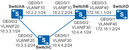
In Figure 1, four switches communicate using RIP on a small-sized network. Services are transmitted through the primary link SwitchA→SwitchB→SwitchD. Reliability must be improved for data transmitted from SwitchA to SwitchB so that services can be rapidly switched to another path when the primary link fails.

In this scenario, ensure that all connected interfaces have STP disabled. If STP is enabled and VLANIF interfaces of switches are used to construct a Layer 3 ring network, an interface on the network will be blocked. As a result, Layer 3 services on the network cannot run normally.
Configuration Roadmap
The configuration roadmap is as follows:
Configure IP address for each interface to ensure network reachability.
Enable RIP on each switch to implement network connections between processes.
Configure BFD for RIP on interfaces at both ends of the link between SwitchA and SwitchB. BFD can rapidly detect the link status and help RIP speed up route convergence to implement fast link switching.
Procedure
- Configure VLANs and add interfaces to the VLANs. The configurations
of SwitchB, SwitchC, and SwitchD are similar to the configuration
of SwitchA, and are not
mentioned here.
<HUAWEI> system-view
[HUAWEI] sysname SwitchA
[SwitchA] vlan batch 10 20
[SwitchA] interface gigabitethernet 0/0/1
[SwitchA-GigabitEthernet0/0/1] port link-type trunk
[SwitchA-GigabitEthernet0/0/1] port trunk allow-pass vlan 10
[SwitchA-GigabitEthernet0/0/1] quit
[SwitchA] interface gigabitethernet 0/0/2
[SwitchA-GigabitEthernet0/0/2] port link-type trunk
[SwitchA-GigabitEthernet0/0/2] port trunk allow-pass vlan 20
[SwitchA-GigabitEthernet0/0/2] quit
- Configure an IP address to each VLANIF interface. The configurations
of SwitchB, SwitchC, and SwitchD are similar to the configuration
of SwitchA, and are not
mentioned here.
[SwitchA] interface vlanif 10
[SwitchA-Vlanif10] ip address 10.2.2.1 24
[SwitchA-Vlanif10] quit
[SwitchA] interface vlanif 20
[SwitchA-Vlanif20] ip address 10.3.3.1 24
[SwitchA-Vlanif20] quit
- Configure basic RIP functions.
# Configure SwitchA.
[SwitchA] rip 1
[SwitchA-rip-1] version 2
[SwitchA-rip-1] network 10.0.0.0
[SwitchA-rip-1] quit
# Configure SwitchB.
[SwitchB] rip 1
[SwitchB-rip-1] version 2
[SwitchB-rip-1] network 10.0.0.0
[SwitchB-rip-1] network 172.16.0.0
[SwitchB-rip-1] quit
# Configure SwitchC.
[SwitchC] rip 1
[SwitchC-rip-1] version 2
[SwitchC-rip-1] network 10.0.0.0
[SwitchC-rip-1] quit
# Configure SwitchD.
[SwitchD] rip 1
[SwitchD-rip-1] version 2
[SwitchD-rip-1] network 172.16.0.0
[SwitchD-rip-1] quit
# After completing the preceding operations, run the display rip neighbor command. The command output shows that SwitchA, SwitchB, and SwitchC have established neighbor relationships with each other. In the following example, the display on SwitchA is used.
[SwitchA] display rip 1 neighbor
---------------------------------------------------------------------
 IP Address      Interface                   Type   Last-Heard-Time
---------------------------------------------------------------------
 10.2.2.2        Vlanif10                    RIP    0:0:14
 Number of RIP routes  : 2
 10.3.3.2        Vlanif20                    RIP    0:0:19
 Number of RIP routes  : 1
# Run the display ip routing-table command. The command output shows that the switches have imported routes from each other. In the following example, the display on SwitchA is used.
[SwitchA] display ip routing-table
Route Flags: R - relay, D - download to fib, T - to vpn-instance
------------------------------------------------------------------------------
Routing Tables: Public
         Destinations : 8        Routes : 9

Destination/Mask    Proto   Pre  Cost      Flags NextHop         Interface

       10.2.2.0/24  Direct  0    0           D   10.2.2.1        Vlanif10
       10.2.2.1/32  Direct  0    0           D   127.0.0.1       Vlanif10
       10.3.3.0/24  Direct  0    0           D   10.3.3.1        Vlanif20
       10.3.3.1/32  Direct  0    0           D   127.0.0.1       Vlanif20
       10.4.4.0/24  RIP     100  1           D   10.3.3.2        Vlanif20
                    RIP     100  1           D   10.2.2.2        Vlanif10
      127.0.0.0/8   Direct  0    0           D   127.0.0.1       InLoopBack0
      127.0.0.1/32  Direct  0    0           D   127.0.0.1       InLoopBack0
     172.16.1.0/24  RIP     100  1           D   10.2.2.2        Vlanif10
The preceding command output shows that the next-hop address and outbound interface of the route to destination 172.16.1.0/24 are 10.2.2.2 and VLANIF10, and traffic is transmitted over the active link SwitchA->SwitchB.
- Configure BFD in RIP processes.
# Configure BFD on all interfaces of SwitchA. The configuration of SwitchB is similar to that of SwitchA, and is not provided here.
[SwitchA] bfd
[SwitchA-bfd] quit
[SwitchA] rip 1
[SwitchA-rip-1] bfd all-interfaces enable
[SwitchA-rip-1] bfd all-interfaces min-tx-interval 100 min-rx-interval 100 detect-multiplier 10
[SwitchA-rip-1] quit
# After completing the preceding operations, run the display rip bfd session command on SwitchA. The command output shows that SwitchA and SwitchB have established a BFD session and the BFDState field displays Up. In the following example, the display on SwitchA is used.
[SwitchA] display rip 1 bfd session all LocalIp : 10.2.2.1 RemoteIp : 10.2.2.2 BFDState : Up TX : 100 RX : 100 Multiplier : 10 BFD Local Dis : 8192 Interface : Vlanif10 Diagnostic Info : No diagnostic information LocalIp : 10.3.3.1 RemoteIp : 10.3.3.2 BFDState : Down TX : 2800 RX : 2800 Multiplier : 0 BFD Local Dis : 8193 Interface : Vlanif20 Diagnostic Info : No diagnostic information - Verify the configuration.
# Run the shutdown command on GigabitEthernet0/0/1 of SwitchB to simulate a fault in the active link.
The link fault is simulated to verify the configuration. In actual situations, the operation is not required.
[SwitchB] interface gigabitethernet 0/0/1
[SwitchB-GigabitEthernet0/0/1] shutdown
# Check the routing table of SwitchA.
[SwitchA] display ip routing-table
Route Flags: R - relay, D - download to fib, T - to vpn-instance
------------------------------------------------------------------------------
Routing Tables: Public
         Destinations : 6        Routes : 6

Destination/Mask    Proto   Pre  Cost      Flags NextHop         Interface

       10.3.3.0/24  Direct  0    0           D   10.3.3.1        Vlanif20
       10.3.3.1/32  Direct  0    0           D   127.0.0.1       Vlanif20
       10.4.4.0/24  RIP     100  1           D   10.3.3.2        Vlanif20
      127.0.0.0/8   Direct  0    0           D   127.0.0.1       InLoopBack0
      127.0.0.1/32  Direct  0    0           D   127.0.0.1       InLoopBack0
     172.16.1.0/24  RIP     100  2           D   10.3.3.2        Vlanif20
The preceding command output shows that the standby link SwitchA->SwitchC->SwitchB is used after the active link fails, and the next-hop address and outbound interface of the route to destination 172.16.1.0/24 are 10.3.3.2 and VLANIF20.
Configuration Files
SwitchA configuration file
#
sysname SwitchA
#
vlan batch 10 20
#
bfd
#
interface Vlanif10
 ip address 10.2.2.1 255.255.255.0
#
interface Vlanif20
 ip address 10.3.3.1 255.255.255.0
#
interface GigabitEthernet0/0/1
 port link-type trunk
 port trunk allow-pass vlan 10
#
interface GigabitEthernet0/0/2
 port link-type trunk
 port trunk allow-pass vlan 20
#
rip 1
 version 2
 network 10.0.0.0
 bfd all-interfaces enable
 bfd all-interfaces min-tx-interval 100 min-rx-interval 100 detect-multiplier 10
#
return
SwitchB configuration file
#
sysname SwitchB
#
vlan batch 10 30 40
#
bfd
#
interface Vlanif10
 ip address 10.2.2.2 255.255.255.0
#
interface Vlanif30
 ip address 10.4.4.1 255.255.255.0
#
interface Vlanif40
 ip address 172.16.1.1 255.255.255.0
#
interface GigabitEthernet0/0/1
 port link-type trunk
 port trunk allow-pass vlan 10
#
interface GigabitEthernet0/0/2
 port link-type trunk
 port trunk allow-pass vlan 30
#
interface GigabitEthernet0/0/3
 port link-type trunk
 port trunk allow-pass vlan 40
#
rip 1
 version 2
 network 10.0.0.0
 network 172.16.0.0
 bfd all-interfaces enable
 bfd all-interfaces min-tx-interval 100 min-rx-interval 100 detect-multiplier 10
#
return
SwitchC configuration file
#
sysname SwitchC
#
vlan batch 20 30
#
interface Vlanif20
 ip address 10.3.3.2 255.255.255.0
#
interface Vlanif30
 ip address 10.4.4.2 255.255.255.0
#
interface GigabitEthernet0/0/1
 port link-type trunk
 port trunk allow-pass vlan 30
#
interface GigabitEthernet0/0/2
 port link-type trunk
 port trunk allow-pass vlan 20
#
rip 1
 version 2
 network 10.0.0.0
#
return
SwitchD configuration file
#
sysname SwitchD
#
vlan batch 40
#
interface Vlanif40
 ip address 172.16.1.2 255.255.255.0
#
interface GigabitEthernet0/0/1
 port link-type trunk
 port trunk allow-pass vlan 40
#
rip 1
 version 2
 network 172.16.0.0
#
return