Example for Configuring RIPng to Filter the Received Routes
Networking Requirements
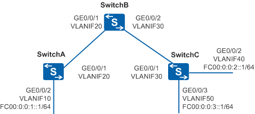
In Figure 1, the prefix length of all the IPv6 addresses is 64 bits, and the VLANIF interfaces between neighboring Switches are assigned IPv6 link-local addresses.
All the Switches must learn IPv6 routing information on the network using RIPng. SwitchB should filter the routes received from SwitchC (at FC00:0:0:3::/64). That is, SwitchB does not add the routes to its own RIPng routing table or advertise the routes to SwitchA.
Configuration Roadmap
The configuration roadmap is as follows:
Enable RIPng on each Switch so that the Switches can communicate with each other.
Configure an ACL on SwitchB to filter the received routes.
Procedure
- Add interfaces to VLANs.
# Configure SwitchA. Ensure that the configurations of SwitchB, and SwitchC are similar to the configuration of SwitchA.
<HUAWEI> system-view
[HUAWEI] sysname SwitchA
[SwitchA] vlan 10
[SwitchA-vlan10] quit
[SwitchA] interface gigabitethernet 0/0/2
[SwitchA-GigabitEthernet0/0/2] port link-type trunk
[SwitchA-GigabitEthernet0/0/2] port trunk allow-pass vlan 10
[SwitchA-GigabitEthernet0/0/2] quit
[SwitchA] vlan 20
[SwitchA-vlan20] quit
[SwitchA] interface gigabitethernet 0/0/1
[SwitchA-GigabitEthernet0/0/1] port link-type trunk
[SwitchA-GigabitEthernet0/0/1] port trunk allow-pass vlan 20
[SwitchA-GigabitEthernet0/0/1] quit
- Assign IP addresses to the VLANIF interfaces.
# Configure SwitchA. Ensure that the configurations of SwitchB, and SwitchC are similar to the configuration of SwitchA.
[SwitchA] ipv6
[SwitchA] interface vlanif 10
[SwitchA-Vlanif10] ipv6 enable
[SwitchA-Vlanif10] ipv6 address fc00:0:0:1::1/64
[SwitchA-Vlanif10] quit
[SwitchA] interface vlanif 20
[SwitchA-Vlanif20] ipv6 enable
[SwitchA-Vlanif20] ipv6 address auto link-local
[SwitchA-Vlanif20] quit
- Configure basic RIPng functions.
# Configure SwitchA.
[SwitchA] ripng 1
[SwitchA-ripng-1] quit
[SwitchA] interface vlanif 10
[SwitchA-Vlanif10] ripng 1 enable
[SwitchA-Vlanif10] quit
[SwitchA] interface vlanif 20
[SwitchA-Vlanif20] ripng 1 enable
[SwitchA-Vlanif20] quit
# Configure SwitchB.
[SwitchB] ripng 1
[SwitchB-ripng-1] quit
[SwitchB] interface vlanif 20
[SwitchB-Vlanif20] ripng 1 enable
[SwitchB-Vlanif20] quit
[SwitchB] interface vlanif 30
[SwitchB-Vlanif30] ripng 1 enable
[SwitchB-Vlanif30] quit
# Configure SwitchC.
[SwitchC] ripng 1
[SwitchC-ripng-1] quit
[SwitchC] interface vlanif 30
[SwitchC-Vlanif30] ripng 1 enable
[SwitchC-Vlanif30] quit
[SwitchC] interface vlanif 40
[SwitchC-Vlanif40] ripng 1 enable
[SwitchC-Vlanif40] quit
[SwitchC] interface vlanif 50
[SwitchC-Vlanif50] ripng 1 enable
[SwitchC-Vlanif50] quit
# Check the RIPng routing table of SwitchB.
[SwitchB] display ripng 1 route
   Route Flags: R - RIPng
                A - Aging, G - Garbage-collect
 ----------------------------------------------------------------
 Peer FE80::D472:0:3C23:1  on Vlanif20
 Dest FC00:0:0:1::/64,
     via FE80::D472:0:3C23:1, cost  1, tag 0, RA, 4 Sec
 Peer FE80::F54C:0:9FDB:1  on Vlanif30
 Dest FC00:0:0:2::/64,
     via FE80::F54C:0:9FDB:1, cost  1, tag 0, RA, 3 Sec
 Dest FC00:0:0:3::/64,
     via FE80::F54C:0:9FDB:1, cost  1, tag 0, RA, 3 Sec
The preceding information shows that the RIPng routing table of SwitchB contains the route of network segment FC00:0:0:3::/64.
# Check the RIPng routing table of SwitchA.
[SwitchA] display ripng 1 route
   Route Flags:  R - RIPng
                A - Aging, G - Garbage-collect
 ----------------------------------------------------------------

 Peer FE80::476:0:3624:1  on Vlanif20
 Dest FC00:0:0:2::/64,
     via FE80::476:0:3624:1, cost  2, tag 0, RA, 21 Sec
 Dest FC00:0:0:3::/64,
     via FE80::476:0:3624:1, cost  2, tag 0, RA, 21 Sec
The preceding information shows that the RIPng routing table of SwitchA contains the route of network segment FC00:0:0:3::/64 advertised by SwitchB.
- Configure SwitchB to filter the received routes.
[SwitchB] acl ipv6 number 2000
[SwitchB-acl6-basic-2000] rule deny source fc00:0:0:3:: 64
[SwitchB-acl6-basic-2000] rule permit
[SwitchB-acl6-basic-2000] quit
[SwitchB] ripng 1
[SwitchB-ripng-1] filter-policy 2000 import
[SwitchB-ripng-1] quit
- Verify the configuration.

After the aging time of the filtered routing entry expires, check the verification result. The default aging time is 180 seconds.
# Check the RIPng routing table of SwitchB. The RIPng routing table should not contain the route of network segment FC00:0:0:3::/64.
[SwitchB] display ripng 1 route
   Route Flags: R - RIPng
                A - Aging, G - Garbage-collect
 ----------------------------------------------------------------
 Peer FE80::D472:0:3C23:1  on Vlanif20
 Dest FC00:0:0:1::/64,
     via FE80::D472:0:3C23:1, cost  1, tag 0, RA, 25 Sec
 Peer FE80::F54C:0:9FDB:1  on Vlanif30
 Dest FC00:0:0:2::/64,
     via FE80::F54C:0:9FDB:1, cost  1, tag 0, RA, 14 Sec
# Check the RIPng routing table of SwitchA. The RIPng routing table should not contain the route of network segment FC00:0:0:3::/64.
[SwitchA] display ripng 1 route
   Route Flags: R - RIPng
                A - Aging, G - Garbage-collect
 ----------------------------------------------------------------

 Peer FE80::476:0:3624:1  on Vlanif20
 Dest FC00:0:0:2::/64,
     via FE80::476:0:3624:1, cost  2, tag 0, RA, 7 Sec
Configuration Files
SwitchA configuration file
#
sysname SwitchA
#
ipv6
#
vlan batch 10 20
#
interface Vlanif10
 ipv6 enable
 ipv6 address FC00:0:0:1::1/64
 ripng 1 enable
#
interface Vlanif20
 ipv6 enable
 ipv6 address auto link-local
 ripng 1 enable
#
interface GigabitEthernet0/0/1
 port link-type trunk
 port trunk allow-pass vlan 20
#
interface GigabitEthernet0/0/2
 port link-type trunk
 port trunk allow-pass vlan 10
#
ripng 1
#
return
SwitchB configuration file
#
sysname SwitchB
#
ipv6
#
vlan batch 20 30
#
acl ipv6 number 2000
 rule 0 deny source FC00:0:0:3::/64
 rule 1 permit
#
interface Vlanif20
 ipv6 enable
 ipv6 address auto link-local
 ripng 1 enable
#
interface Vlanif30
 ipv6 enable
 ipv6 address auto link-local
 ripng 1 enable
#
interface GigabitEthernet0/0/1
 port link-type trunk
 port trunk allow-pass vlan 20
#
interface GigabitEthernet0/0/2
 port link-type trunk
 port trunk allow-pass vlan 30
#
ripng 1
 filter-policy 2000 import
#
return
SwitchC configuration file
#
sysname SwitchC
#
ipv6
#
vlan batch 30 40 50
#
interface Vlanif30
 ipv6 enable
 ipv6 address auto link-local
 ripng 1 enable
#
interface Vlanif40
 ipv6 enable
 ipv6 address FC00:0:0:2::1/64
 ripng 1 enable
#
interface Vlanif50
 ipv6 enable
 ipv6 address FC00:0:0:3::1/64
 ripng 1 enable
#
interface GigabitEthernet0/0/1
 port link-type trunk
 port trunk allow-pass vlan 30
#
interface GigabitEthernet0/0/2
 port link-type trunk
 port trunk allow-pass vlan 40
#
interface GigabitEthernet0/0/3
 port link-type trunk
 port trunk allow-pass vlan 50
#
ripng 1
#
return