Example for Configuring Association Between IPv4 Static Routes and a Route Monitoring Group
Networking Requirements
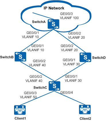
On a company's network shown in Figure 1, SwitchC at the access layer connects to SwtichB and SwitchD at the aggregation layer through static routes. SwtichB and SwitchD work in redundancy mode. The customer requirements are as follows:
A link failure detection mechanism is deployed for static routes, so that traffic can be switched from a faulty link to a normal link in a timely manner to prevent service interruption for a long time.
In normal situations, service traffic from the access side is forwarded to the IP network through SwitchB.
If the link between SwitchB and SwitchA fails, only the link between SwitchD and the IP network is available. In this case, service traffic from the access side is switched to SwitchD to prevent traffic loss.
Device Name |
Interface |
IP Address |
|---|---|---|
SwitchA |
VLANIF 10 |
192.168.10.1/24 |
VLANIF 20 |
192.168.20.1/24 |
|
VLANIF 100 |
192.168.100.1/24 |
|
SwitchB |
VLANIF 10 |
192.168.10.2/24 |
VLANIF 40 |
192.168.40.1/24 |
|
SwitchC |
VLANIF 30 |
192.168.30.2/24 |
VLANIF 40 |
192.168.40.2/24 |
|
VLANIF 50 |
192.168.50.1/24 |
|
SwitchD |
VLANIF 20 |
192.168.20.2/24 |
VLANIF 30 |
192.168.30.1/24 |
Configuration Roadmap
The configuration roadmap is as follows:
Create VLANs, add interfaces to the VLANs, and configure IP addresses for VLANIF interfaces, so that neighboring devices can communicate with each other.
- Configure static routes and bind them to a route monitoring group. On SwitchC, configure static routes, set a low cost for the route corresponding to the active link, and bind the static routes to a route monitoring group. In this way, the links can work in active/standby mode, and IPv4 static routes are associated with the route monitoring group.
Procedure
- Configure VLANs to which interfaces belong.
# Configure SwitchC. The configurations of other devices are similar to those of SwitchC.
<HUAWEI> system-view
[HUAWEI] sysname SwitchC
[SwitchC] vlan batch 30 40 50
[SwitchC] interface gigabitethernet 0/0/1
[SwitchC-gigabitethernet0/0/1] port link-type trunk
[SwitchC-gigabitethernet0/0/1] port trunk allow-pass vlan 30
[SwitchC-gigabitethernet0/0/1] quit
[SwitchC] interface gigabitethernet 0/0/2
[SwitchC-gigabitethernet0/0/2] port link-type trunk
[SwitchC-gigabitethernet0/0/2] port trunk allow-pass vlan 40
[SwitchC-gigabitethernet0/0/2] quit
[SwitchC] interface gigabitethernet 0/0/3
[SwitchC-gigabitethernet0/0/3] port link-type trunk
[SwitchC-gigabitethernet0/0/3] port trunk allow-pass vlan 50
[SwitchC-gigabitethernet0/0/3] quit
- Configure an IP address for each VLANIF interface.# Configure SwitchC. The configurations of other devices are similar to those of SwitchC.
[SwitchC] interface vlanif 30
[SwitchC-Vlanif10] ip address 192.168.30.2 24
[SwitchC-Vlanif10] quit
[SwitchC] interface vlanif 40
[SwitchC-Vlanif40] ip address 192.168.40.2 24
[SwitchC-Vlanif40] quit
[SwitchC] interface vlanif 50
[SwitchC-Vlanif50] ip address 192.168.50.1 24
[SwitchC-Vlanif50] quit
- Configure static routes and bind them to a route monitoring group.
# On SwitchC, add routes to be monitored to the route monitoring group uplink.
[SwitchC-route-monitor-group-uplink] track ip route 192.168.100.0 255.255.255.0# On SwitchC, enable the route monitoring group.
[SwitchC-route-monitor-group-uplink] monitor enable
[SwitchC-route-monitor-group-uplink] quit
# On SwitchC, configure static routes to the external network and bind the static routes to the route monitoring group uplink.
[SwitchC] ip route-static 192.168.100.0 255.255.255.0 192.168.40.1 preference 50 track route-monitor-group uplink
[SwitchC] ip route-static 192.168.100.0 255.255.255.0 192.168.30.1
# On SwitchB, configure a static route to Client1.
<HUAWEI> system-view
[HUAWEI] sysname SwitchB
[SwitchB] ip route-static 192.168.50.0 255.255.255.0 192.168.40.2
# On SwitchD, configure a static route to Client1.
<HUAWEI> system-view
[HUAWEI] sysname SwitchD
[SwitchD] ip route-static 192.168.50.0 255.255.255.0 192.168.30.2
- Verify the configuration.
# Check information about the route monitoring group uplink on SwitchC. The command output shows that the route monitoring group has been enabled and the route to 192.168.100.0/24 is an active route.
[SwitchC] display ip route-monitor-group uplink
route monitor group uplink
 State        : Enabled
-------------------------------------------------------
 route monitor group tracking route number : 1
-------------------------------------------------------
 VPN name     : Public
 Destination  : 192.168.100.0
 Mask         : 255.255.255.0
 State        : Active
# Check information about static routes on SwitchC to determine the active and standby links.
[SwitchC] display ip routing-table protocol static
Route Flags: R - relay, D - download to fib, T - to vpn-instance
------------------------------------------------------------------------------
Public routing table : Static
         Destinations : 1        Routes : 2        Configured Routes : 6

Static routing table status : <Active>
         Destinations : 1        Routes : 1

Destination/Mask    Proto   Pre  Cost      Flags NextHop         Interface

   192.168.100.0/24 Static  50   0           D   192.168.40.1    Vlanif40

Static routing table status : <Inactive>
         Destinations : 1        Routes : 1

Destination/Mask    Proto   Pre  Cost      Flags NextHop         Interface

   192.168.100.0/24 Static  60   0               192.168.30.1    Vlanif30
# Disable gigabitethernet0/0/1 on SwitchB to simulate a link failure.
[SwitchB] interface gigabitethernet 0/0/1
[SwitchB-gigabitethernet0/0/1] shutdown
[SwitchB-gigabitethernet0/0/1] quit
# Check information about the route monitoring group uplink on SwitchC. The command output shows that the route status corresponding to the faulty link is Inactive.
[SwitchC] display ip route-monitor-group uplink
route monitor group uplink
 State        : Enabled
-------------------------------------------------------
 route monitor group tracking route number : 1
-------------------------------------------------------
 VPN name     : Public
 Destination  : 192.168.100.0
 Mask         : 255.255.255.0
 State        : Inactive
# Check information about static routes on SwitchC. The command output shows that static routes on SwitchC have been bound to a route monitoring group. If the route monitoring group detects a link failure, the RM module immediately notifies the access device that the corresponding route is unavailable.
[SwitchC] display ip routing-table protocol static
Route Flags: R - relay, D - download to fib, T - to vpn-instance
------------------------------------------------------------------------------
Public routing table : Static
         Destinations : 1        Routes : 2        Configured Routes : 6

Static routing table status : <Active>
         Destinations : 1        Routes : 1

Destination/Mask    Proto   Pre  Cost      Flags NextHop         Interface

  192.168.100.0/24   Static  60   0           D  192.168.30.1    Vlanif40

Static routing table status : <Inactive>
         Destinations : 1        Routes : 1

Destination/Mask    Proto   Pre  Cost      Flags NextHop         Interface

  192.168.100.0/24   Static  50   0              192.168.40.1    Vlanif30
Configuration Files
-
#
sysname SwitchA
#
vlan batch 10 20 100
#
interface Vlanif10
 ip address 192.168.100.1 255.255.255.0
#
interface Vlanif20
 ip address 192.168.20.1 255.255.255.0
#
interface Vlanif100
 ip address 192.168.100.1 255.255.255.0
#
interface GigabitEthernet0/0/1
 port link-type trunk
 port trunk allow-pass vlan 10
#
interface GigabitEthernet0/0/2
 port link-type trunk
 port trunk allow-pass vlan 20
#
interface GigabitEthernet0/0/3
 port link-type trunk
 port trunk allow-pass vlan 100
#
return
-
#
sysname SwitchB
#
vlan batch 10 40
#
interface Vlanif10
 ip address 192.168.10.2 255.255.255.0
#
interface Vlanif40
 ip address 192.168.40.1 255.255.255.0
#
interface GigabitEthernet0/0/1
 port link-type trunk
 port trunk allow-pass vlan 10
#
interface GigabitEthernet0/0/2
 port link-type trunk
 port trunk allow-pass vlan 40
#
ip route-static 192.168.50.0 255.255.255.0 192.168.40.2
return
-
#
sysname SwitchC
#
vlan batch 30 40 50
#
interface Vlanif30
 ip address 192.168.30.2 255.255.255.0
#
interface Vlanif40
 ip address 192.168.40.2 255.255.255.0
#
interface Vlanif50
 ip address 192.168.50.1 255.255.255.0
#
interface GigabitEthernet0/0/1
 port link-type trunk
 port trunk allow-pass vlan 30
#
interface GigabitEthernet0/0/2
 port link-type trunk
 port trunk allow-pass vlan 40
#
interface GigabitEthernet0/0/3
 port link-type trunk
 port trunk allow-pass vlan 50
#
ip route-monitor-group uplink
 track ip route 192.168.10.0 255.255.255.0
 monitor enable
#
ip route-static 192.168.100.0 255.255.255.0 192.168.30.1 preference 50 track route-monitor-group uplink
ip route-static 192.168.100.0 255.255.255.0 192.168.40.1
#
return
-
#
sysname SwitchD
#
vlan batch 20 30
#
interface Vlanif20
 ip address 192.168.20.2 255.255.255.0
#
interface Vlanif30
 ip address 192.168.30.1 255.255.255.0
#
interface GigabitEthernet0/0/1
 port link-type trunk
 port trunk allow-pass vlan 30
#
interface GigabitEthernet0/0/2
 port link-type trunk
 port trunk allow-pass vlan 20
#
ip route-static 192.168.50.0 255.255.255.0 192.168.30.2
#
return