Example for Applying a Routing Policy for Importing Routes
Networking Requirements
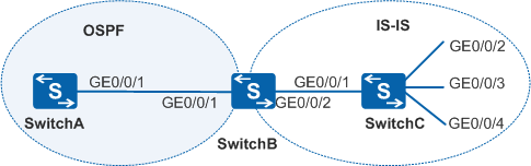
In Figure 1, SwitchB exchanges routing information with SwitchA through OSPF, and with SwitchC through IS-IS. A user wants SwitchB to import IS-IS routes into the OSPF network. The user also wants the route to 172.17.1.0/24 on the OSPF network to have a low preference and the route to 172.17.2.0/24 to have a tag, making it easy to reference by a routing policy.
Device |
Interface |
VLANIF Interface |
IP Address |
SwitchA |
GE0/0/1 |
VLANIF10 |
192.168.1.1/24 |
SwitchB |
GE0/0/1 |
VLANIF10 |
192.168.1.2/24 |
SwitchB |
GE0/0/2 |
VLANIF20 |
192.168.2.2/24 |
SwitchC |
GE0/0/1 |
VLANIF20 |
192.168.2.1/24 |
SwitchC |
GE0/0/2 |
VLANIF30 |
172.17.1.1/24 |
SwitchC |
GE0/0/3 |
VLANIF40 |
172.17.2.1/24 |
SwitchC |
GE0/0/4 |
VLANIF50 |
172.17.3.1/24 |
Configuration Roadmap
The configuration roadmap is as follows:
Configure a routing policy on SwitchB, set the cost of the route to 172.17.1.0/24 to 100, and apply the routing policy when OSPF imports IS-IS routes. The routing policy allows the route to 172.17.1.0/24 to have a low preference.
Configure a routing policy on SwitchB, set the tag of the route to 172.17.2.0/24 to 20, and apply the routing policy when OSPF imports IS-IS routes. This allows the tag of the route to 172.17.2.0/24 to take effect, making it easy to reference by a routing policy.
Procedure
- Add interfaces to VLANs.
# Configure SwitchA. Ensure that the configurations of SwitchB, and SwitchC are the same as the configuration of SwitchA.
<HUAWEI> system-view
[HUAWEI] sysname SwitchA
[SwitchA] vlan batch 10
[SwitchA] interface gigabitethernet 0/0/1
[SwitchA-GigabitEthernet0/0/1] port link-type trunk
[SwitchA-GigabitEthernet0/0/1] port trunk allow-pass vlan 10
[SwitchA-GigabitEthernet0/0/1] quit
- Assign IP addresses to VLANIF interfaces.
# Configure SwitchA. Ensure that the configurations of SwitchB, and SwitchC are the same as the configuration of SwitchA.
[SwitchA] interface vlanif 10
[SwitchA-Vlanif10] ip address 192.168.1.1 24
[SwitchA-Vlanif10] quit
- Configure IS-IS.
# Configure SwitchC.
[SwitchC] isis
[SwitchC-isis-1] is-level level-2
[SwitchC-isis-1] network-entity 10.0000.0000.0001.00
[SwitchC-isis-1] quit
[SwitchC] interface vlanif 20
[SwitchC-Vlanif20] isis enable
[SwitchC-Vlanif20] quit
[SwitchC] interface vlanif 30
[SwitchC-Vlanif30] isis enable
[SwitchC-Vlanif30] quit
[SwitchC] interface vlanif 40
[SwitchC-Vlanif40] isis enable
[SwitchC-Vlanif40] quit
[SwitchC] interface vlanif 50
[SwitchC-Vlanif50] isis enable
[SwitchC-Vlanif50] quit
# Configure SwitchB.
[SwitchB] isis
[SwitchB-isis-1] is-level level-2
[SwitchB-isis-1] network-entity 10.0000.0000.0002.00
[SwitchB-isis-1] quit
[SwitchB] interface vlanif 20
[SwitchB-Vlanif20] isis enable
[SwitchB-Vlanif20] quit
- Configure OSPF and import routes.
# Configure SwitchA and enable OSPF.
[SwitchA] ospf
[SwitchA-ospf-1] area 0
[SwitchA-ospf-1-area-0.0.0.0] network 192.168.1.0 0.0.0.255
[SwitchA-ospf-1-area-0.0.0.0] quit
[SwitchA-ospf-1] quit
# Configure SwitchB, enable OSPF, and import IS-IS routes.
[SwitchB] ospf
[SwitchB-ospf-1] area 0
[SwitchB-ospf-1-area-0.0.0.0] network 192.168.1.0 0.0.0.255
[SwitchB-ospf-1-area-0.0.0.0] quit
[SwitchB-ospf-1] import-route isis 1
[SwitchB-ospf-1] quit
# Check the OSPF routing table on SwitchA. You can see the imported routes.
[SwitchA] display ospf routing OSPF Process 1 with Router ID 192.168.1.1 Routing Tables Routing for Network Destination Cost Type NextHop AdvRouter Area 192.168.1.0/24 1 Transit 192.168.1.1 192.168.1.1 0.0.0.0 Routing for ASEs Destination Cost Type Tag NextHop AdvRouter 172.17.1.0/24 1 Type2 1 192.168.1.2 192.168.1.2 172.17.2.0/24 1 Type2 1 192.168.1.2 192.168.1.2 172.17.3.0/24 1 Type2 1 192.168.1.2 192.168.1.2 192.168.2.0/24 1 Type2 1 192.168.1.2 192.168.1.2 Total Nets: 5 Intra Area: 1 Inter Area: 0 ASE: 4 NSSA: 0 - Set the filtering list.
# Configure ACL 2002 to match 172.17.2.0/24.
[SwitchB] acl number 2002
[SwitchB-acl-basic-2002] rule permit source 172.17.2.0 0.0.0.255
[SwitchB-acl-basic-2002] quit
# Configure an IP prefix list named prefix-a to match 172.17.1.0/24.
[SwitchB] ip ip-prefix prefix-a index 10 permit 172.17.1.0 24 - Configure a routing policy.
[SwitchB] route-policy isis2ospf permit node 10
[SwitchB-route-policy] if-match ip-prefix prefix-a
[SwitchB-route-policy] apply cost 100
[SwitchB-route-policy] quit
[SwitchB] route-policy isis2ospf permit node 20
[SwitchB-route-policy] if-match acl 2002
[SwitchB-route-policy] apply tag 20
[SwitchB-route-policy] quit
[SwitchB] route-policy isis2ospf permit node 30
[SwitchB-route-policy] quit
- Apply the routing policy when routes are imported.
# Configure SwitchB and apply the routing policy when routes are imported.
[SwitchB] ospf
[SwitchB-ospf-1] import-route isis 1 route-policy isis2ospf
[SwitchB-ospf-1] quit
# Check the OSPF routing table on SwitchA. You can see that the cost of the route to 172.17.1.0/24 is 100; the tag of the route to 172.17.2.0/24 is 20; other route attributes remain unchanged.
[SwitchA] display ospf routing

          OSPF Process 1 with Router ID 192.168.1.1
                   Routing Tables

 Routing for Network
 Destination        Cost  Type       NextHop         AdvRouter       Area
 192.168.1.0/24     1     Transit    192.168.1.1     192.168.1.1     0.0.0.0

 Routing for ASEs
 Destination        Cost      Type       Tag         NextHop           AdvRouter
 172.17.1.0/24      100       Type2      1           192.168.1.2       192.168.1.2
 172.17.2.0/24      1         Type2      20          192.168.1.2       192.168.1.2
 172.17.3.0/24      1         Type2      1           192.168.1.2       192.168.1.2
 192.168.2.0/24     1         Type2      1           192.168.1.2       192.168.1.2

 Total Nets: 5
 Intra Area: 1  Inter Area: 0  ASE: 4  NSSA: 0
Configuration Files
Configuration file of SwitchA
#
sysname SwitchA
#
vlan batch 10
#
interface Vlanif10
 ip address 192.168.1.1 255.255.255.0
#
interface GigabitEthernet0/0/1
 port link-type trunk
 port trunk allow-pass vlan 10
#
ospf 1
 area 0.0.0.0
  network 192.168.1.0 0.0.0.255
#
return
Configuration file of SwitchB
#
sysname SwitchB
#
vlan batch 10 20
#
acl number 2002
 rule 5 permit source 172.17.2.0 0.0.0.255
#
isis 1
 is-level level-2
 network-entity 10.0000.0000.0002.00
#
interface Vlanif10
 ip address 192.168.1.2 255.255.255.0
#
interface Vlanif20
 ip address 192.168.2.2 255.255.255.0
 isis enable 1
#
interface GigabitEthernet0/0/1
 port link-type trunk
 port trunk allow-pass vlan 10
#
interface GigabitEthernet0/0/2
 port link-type trunk
 port trunk allow-pass vlan 20
#
ospf 1
 import-route isis 1 route-policy isis2ospf
 area 0.0.0.0
  network 192.168.1.0 0.0.0.255
#
route-policy isis2ospf permit node 10
 if-match ip-prefix prefix-a
 apply cost 100
#
route-policy isis2ospf permit node 20
 if-match acl 2002
 apply tag 20
#
route-policy isis2ospf permit node 30
#
ip ip-prefix prefix-a index 10 permit 172.17.1.0 24
#
return
Configuration file of SwitchC
#
sysname SwitchC
#
vlan batch 20 30 40 50
#
isis 1
 is-level level-2
 network-entity 10.0000.0000.0001.00
#
interface Vlanif20
 ip address 192.168.2.1 255.255.255.0
 isis enable 1
#
interface Vlanif30
 ip address 172.17.1.1 255.255.255.0
 isis enable 1
#
interface Vlanif40
 ip address 172.17.2.1 255.255.255.0
 isis enable 1
#
interface Vlanif50
 ip address 172.17.3.1 255.255.255.0
 isis enable 1
#
interface GigabitEthernet0/0/1
 port link-type trunk
 port trunk allow-pass vlan 20
#
interface GigabitEthernet0/0/2
 port link-type trunk
 port trunk allow-pass vlan 30
#
interface GigabitEthernet0/0/3
 port link-type trunk
 port trunk allow-pass vlan 40
#
interface GigabitEthernet0/0/4
 port link-type trunk
 port trunk allow-pass vlan 50
#
return