Example for Configuring Tangent RRPP Rings with Multiple Instances
Networking Requirements
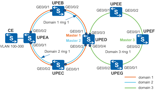
As shown in Figure 1, on a ring network, idle links are required to forward data. In this way, data in different VLANs are forwarded along different paths, improving network efficiency and implementing load balancing.
Data Plan
Table 1 shows the mapping between protected VLANs and instances in Domain 1, Domain 2, and Domain 3.
Domain ID |
Control VLAN |
Data VLAN |
Instance ID |
|---|---|---|---|
Domain 1 |
VLANs 5 and 6 |
VLANs 100 to 200 |
Instance 1 |
Domain 2 |
VLANs 10 and 11 |
VLANs 201 to 300 |
Instance 2 |
Domain 3 (on UPED) |
VLANs 20 and 21 |
VLANs 100 to 300 |
Instance 1, Instance 2, and Instance 3 |
Domain 3 (on UPEE, UPEF, and UPEG) |
VLANs 20 and 21 |
VLANs 100 to 300 |
Instance 1 |
Table 2 shows the master node on each ring, and its primary and secondary interfaces.
Configuration Roadmap
The configuration roadmap is as follows:
Create different RRPP domains and control VLANs.
Map the VLANs that need to pass through the domain to the instance.
Configure interfaces to be added to the RRPP domain on the devices so that data can pass through the interfaces. Disable protocols that conflict with RRPP, such as STP.
- Configure protected VLANs and create RRPP rings in RRPP domains.
Add UPEA, UPEB, UPEC, and UPED to Ring 1 in Domain 1 and Ring 1 in Domain 2.
Add UPED, UPEE, UPEF, and UPEG to Ring 1 in Domain 3.
Configure UPED as the master node and configure UPEA, UPEB, and UPEC as transit nodes on Ring 1 in Domain 1 and Ring 1 in Domain 2.
Configure UPEF as the master node and configure UPED, UPEE, and UPEG as transit nodes on Ring 1 in Domain 3.
Enable the RRPP ring and RRPP protocol on devices to make RRPP take effect.
Procedure
- Configure instances, and map it to the data VLANs and control
VLANs allowed by the RRPP interface.
# Configure UPEA. The configurations on UPEB, UPEC, UPED, UPEE, UPEF, and UPEG are the same as that of UPEA and not mentioned here. For details, see the configuration files.
<HUAWEI> system-view
[HUAWEI] sysname UPEA
[UPEA] stp region-configuration
[UPEA-mst-region] instance 1 vlan 5 6 100 to 200
[UPEA-mst-region] instance 2 vlan 10 11 201 to 300
[UPEA-mst-region] active region-configuration
[UPEA-mst-region] quit
- Configure the interfaces to be added into the RRPP rings.
# Configure UPEA. The configurations on UPEB, UPEC, UPED, UPEE, UPEF, and UPEG are the same as that of UPEA and not mentioned here. For details, see the configuration files.
[UPEA] vlan batch 100 to 300
[UPEA] interface gigabitethernet 0/0/1
[UPEA-GigabitEthernet0/0/1] port link-type trunk
[UPEA-GigabitEthernet0/0/1] undo port trunk allow-pass vlan 1
[UPEA-GigabitEthernet0/0/1] port trunk allow-pass vlan 100 to 300
[UPEA-GigabitEthernet0/0/1] stp disable
[UPEA-GigabitEthernet0/0/1] quit
[UPEA] interface gigabitethernet 0/0/2
[UPEA-GigabitEthernet0/0/2] port link-type trunk
[UPEA-GigabitEthernet0/0/2] undo port trunk allow-pass vlan 1
[UPEA-GigabitEthernet0/0/2] port trunk allow-pass vlan 100 to 300
[UPEA-GigabitEthernet0/0/2] stp disable
[UPEA-GigabitEthernet0/0/2] quit
- Create RRPP domains and configure protected VLANs and control
VLANs.
# Configure UPEA. The configurations on UPEB, UPEC, UPED, UPEE, UPEF, and UPEG are similar to that on UPEA and not mentioned here. For details, see the configuration files.
[UPEA] rrpp domain 1
[UPEA-rrpp-domain-region1] protected-vlan reference-instance 1
[UPEA-rrpp-domain-region1] control-vlan 5
[UPEA-rrpp-domain-region1] quit
[UPEA] rrpp domain 2
[UPEA-rrpp-domain-region2] protected-vlan reference-instance 2
[UPEA-rrpp-domain-region2] control-vlan 10
[UPEA-rrpp-domain-region2] quit
- Create RRPP rings.
# Configure UPEA as a transit node on Ring 1 in Domain 1 and specify primary and secondary interfaces on UPEA.
[UPEA] rrpp domain 1
[UPEA-rrpp-domain-region1] ring 1 node-mode transit primary-port gigabitethernet 0/0/1 secondary-port gigabitethernet 0/0/2 level 0
[UPEA-rrpp-domain-region1] ring 1 enable
[UPEA-rrpp-domain-region1] quit
# Configure UPEA as a transit node on Ring 1 in Domain 2 and specify primary and secondary interfaces on UPEA.
[UPEA] rrpp domain 2
[UPEA-rrpp-domain-region2] ring 1 node-mode transit primary-port gigabitethernet 0/0/1 secondary-port gigabitethernet 0/0/2 level 0
[UPEA-rrpp-domain-region2] ring 1 enable
[UPEA-rrpp-domain-region2] quit
# Configure UPEB as a transit node on Ring 1 in Domain 1 and specify primary and secondary interfaces on UPEB.
[UPEB] rrpp domain 1
[UPEB-rrpp-domain-region1] ring 1 node-mode transit primary-port gigabitethernet 0/0/1 secondary-port gigabitethernet 0/0/2 level 0
[UPEB-rrpp-domain-region1] ring 1 enable
[UPEB-rrpp-domain-region1] quit
# Configure UPEB as a transit node on Ring 1 in Domain 2 and specify primary and secondary interfaces on UPEB.
[UPEB] rrpp domain 2
[UPEB-rrpp-domain-region2] ring 1 node-mode transit primary-port gigabitethernet 0/0/1 secondary-port gigabitethernet 0/0/2 level 0
[UPEB-rrpp-domain-region2] ring 1 enable
[UPEB-rrpp-domain-region2] quit
# Configure UPEC as a transit node on Ring 1 in Domain 1 and specify primary and secondary interfaces on UPEC.
[UPEC] rrpp domain 1
[UPEC-rrpp-domain-region1] ring 1 node-mode transit primary-port gigabitethernet 0/0/1 secondary-port gigabitethernet 0/0/2 level 0
[UPEC-rrpp-domain-region1] ring 1 enable
[UPEC-rrpp-domain-region1] quit
# Configure UPEC as a transit node on Ring 1 in Domain 2 and specify primary and secondary interfaces on UPEC.
[UPEC] rrpp domain 2
[UPEC-rrpp-domain-region2] ring 1 node-mode transit primary-port gigabitethernet 0/0/1 secondary-port gigabitethernet 0/0/2 level 0
[UPEC-rrpp-domain-region2] ring 1 enable
[UPEC-rrpp-domain-region2] quit
# Configure UPED as the master node on Ring 1 in Domain 1 and specify GE0/0/1 as the primary interface and GE0/0/2 as the secondary interface on UPED.
[UPED] rrpp domain 1
[UPED-rrpp-domain-region1] ring 1 node-mode master primary-port gigabitethernet 0/0/1 secondary-port gigabitethernet 0/0/2 level 0
[UPED-rrpp-domain-region1] ring 1 enable
[UPED-rrpp-domain-region1] quit
# Configure UPED as the master node on Ring 1 in Domain 2 and specify GE0/0/2 as the primary interface and GE0/0/1 as the secondary interface on UPED.
[UPED] rrpp domain 2
[UPED-rrpp-domain-region2] ring 1 node-mode master primary-port gigabitethernet 0/0/2 secondary-port gigabitethernet 0/0/1 level 0
[UPED-rrpp-domain-region2] ring 1 enable
[UPED-rrpp-domain-region2] quit
# Configure UPED as a transit node on Ring 1 in Domain 3 and specify primary and secondary interfaces on UPED.
[UPED] rrpp domain 3
[UPED-rrpp-domain-region3] ring 1 node-mode transit primary-port gigabitethernet 0/0/3 secondary-port gigabitethernet 0/0/4 level 0
[UPED-rrpp-domain-region3] ring 1 enable
[UPED-rrpp-domain-region3] quit
# Configure UPEE as a transit node on Ring 1 in Domain 3 and specify primary and secondary interfaces on UPEE.
[UPEE] rrpp domain 3
[UPEE-rrpp-domain-region3] ring 1 node-mode transit primary-port gigabitethernet 0/0/1 secondary-port gigabitethernet 0/0/2 level 0
[UPEE-rrpp-domain-region3] ring 1 enable
[UPEE-rrpp-domain-region3] quit
# Configure UPEF as the master node on Ring 1 in Domain 3 and specify GE0/0/1 as the primary interface and GE0/0/2 as the secondary interface on UPEF.
[UPEF] rrpp domain 3
[UPEF-rrpp-domain-region3] ring 1 node-mode master primary-port gigabitethernet 0/0/1 secondary-port gigabitethernet 0/0/2 level 0
[UPEF-rrpp-domain-region3] ring 1 enable
[UPEF-rrpp-domain-region3] quit
# Configure UPEG as a transit node on Ring 1 in Domain 3 and specify primary and secondary interfaces.
[UPEG] rrpp domain 3
[UPEG-rrpp-domain-region3] ring 1 node-mode transit primary-port gigabitethernet 0/0/1 secondary-port gigabitethernet 0/0/2 level 0
[UPEG-rrpp-domain-region3] ring 1 enable
[UPEG-rrpp-domain-region3] quit
- Enable RRPP.
# Configure UPEA. The configurations on UPEB, UPEC, UPED, UPEE, UPEF, and UPEG are the same as that of UPEA and not mentioned here. For details, see the configuration files.
[UPEA] rrpp enable
- Verify the configuration.
After the preceding configurations are complete and the network topology becomes stable, perform the following operations to verify the configuration. UPED is used as an example.
# Run the display rrpp brief command on UPED. The command output is as follows:
[UPED] display rrpp brief
Abbreviations for Switch Node Mode :
M - Master , T - Transit , E - Edge , A - Assistant-Edge

RRPP Protocol Status: Enable
RRPP Working Mode: HW
RRPP Linkup Delay Timer: 0 sec (0 sec default)
Number of RRPP Domains: 3

Domain Index   : 1
Control VLAN   : major 5    sub 6
Protected VLAN : Reference Instance 1
Hello Timer    : 1 sec(default is 1 sec)  Fail Timer : 6 sec(default is 6 sec)

Ring   Ring    Node     Primary/Common           Secondary/Edge          Is
ID     Level   Mode     Port                     Port                    Enabled
----------------------------------------------------------------------------
1      0       M        GigabitEthernet0/0/1     GigabitEthernet0/0/2    Yes

Domain Index   : 2
Control VLAN   : major 10    sub 11
Protected VLAN : Reference Instance 2
Hello Timer    : 1 sec(default is 1 sec)  Fail Timer : 6 sec(default is 6 sec)

Ring   Ring    Node     Primary/Common           Secondary/Edge          Is
ID     Level   Mode     Port                     Port                    Enabled
----------------------------------------------------------------------------
1      0       M        GigabitEthernet0/0/2     GigabitEthernet0/0/1    Yes

Domain Index   : 3
Control VLAN   : major 20    sub 21
Protected VLAN : Reference Instance 1 to 3
Hello Timer    : 1 sec(default is 1 sec)  Fail Timer : 6 sec(default is 6 sec)

Ring   Ring    Node     Primary/Common           Secondary/Edge          Is
ID     Level   Mode     Port                     Port                    Enabled
----------------------------------------------------------------------------
1      0       T        GigabitEthernet0/0/3     GigabitEthernet0/0/4    Yes
The command output shows that RRPP is enabled on UPED.
In Domain 1:
The major control VLAN is VLAN 5, and the protected VLANs are the VLANs mapped to Instance 1.
UPED is the master node on Ring 1. GigabitEthernet0/0/1 is the primary interface and GigabitEthernet0/0/2 is the secondary interface.
In Domain 2:
The major control VLAN is VLAN 10, and the protected VLANs are the VLANs mapped to Instance 2.
UPED is the master node on Ring 1. GigabitEthernet0/0/2 is the primary interface and GigabitEthernet0/0/1 is the secondary interface.
In Domain 3:
The major control VLAN is VLAN 20, and the protected VLANs are the VLANs mapped to instances 1 to 3.
UPED is a transit node on Ring 1. GigabitEthernet0/0/3 is the primary interface and GigabitEthernet0/0/4 is the secondary interface.
Run the display rrpp verbose domain command on UPED. The command output is as follows:
# Check detailed information about UPED in Domain 1.
[UPED] display rrpp verbose domain 1
Domain Index   : 1
Control VLAN   : major 5    sub 6
Protected VLAN : Reference Instance 1
Hello Timer    : 1 sec(default is 1 sec)  Fail Timer : 6 sec(default is 6 sec)

RRPP Ring      : 1
Ring Level     : 0
Node Mode      : Master
Ring State     : Complete
Is Enabled     : Enable                             Is Active: Yes
Primary port   : GigabitEthernet0/0/1               Port status: UP
Secondary port : GigabitEthernet0/0/2               Port status: BLOCKED
The command output shows that the control VLAN in Domain 1 is VLAN 5, and the protected VLANs are the VLANs mapping Instance 1.
UPED is the master node in Domain 1 and is in Complete state.
The primary interface is GigabitEthernet0/0/1 and the secondary interface is GigabitEthernet0/0/2.
# Check detailed information about UPED in Domain 2.
[UPED] display rrpp verbose domain 2
Domain Index   : 2
Control VLAN   : major 10    sub 11
Protected VLAN : Reference Instance 2
Hello Timer    : 1 sec(default is 1 sec)  Fail Timer : 6 sec(default is 6 sec)

RRPP Ring      : 1
Ring Level     : 0
Node Mode      : Master
Ring State     : Complete
Is Enabled     : Enable                             Is Active: Yes
Primary port   : GigabitEthernet0/0/2               Port status: UP
Secondary port : GigabitEthernet0/0/1               Port status: BLOCKED
The command output shows that, in Domain 2, the control VLAN is VLAN 10, and the protected VLAN is the VLAN mapped to Instance 2.
UPED is the master node in Domain 2 and is in Complete state.
The primary interface is GigabitEthernet0/0/2 and the secondary interface is GigabitEthernet0/0/1.
# Check detailed information about UPED in Domain 3.
[UPED] display rrpp verbose domain 3
Domain Index   : 3
Control VLAN   : major 20    sub 21
Protected VLAN : Reference Instance 1 to 3
Hello Timer    : 1 sec(default is 1 sec)  Fail Timer : 6 sec(default is 6 sec)

RRPP Ring      : 1
Ring Level     : 0
Node Mode      : Transit
Ring State     : LinkUp
Is Enabled     : Enable                             Is Active: Yes
Primary port   : GigabitEthernet0/0/3               Port status: UP
Secondary port : GigabitEthernet0/0/4               Port status: UP
The command output shows that, in Domain 3, the control VLAN is VLAN 20 and the protected VLANs are the VLANs mapped to instances 1 to 3.
UPED is a transit node in Domain 3 and is in LinkUp state.
The primary interface is GigabitEthernet0/0/3 and the secondary interface is GigabitEthernet0/0/4.
Configuration Files
UPEA configuration file
#
sysname UPEA
#
vlan batch 5 to 6 10 to 11 100 to 300
#
rrpp enable
#
stp region-configuration
 instance 1 vlan 5 to 6 100 to 200
 instance 2 vlan 10 to 11 201 to 300
 active region-configuration
#
rrpp domain 1
 control-vlan 5
 protected-vlan reference-instance 1
 ring 1 node-mode transit primary-port GigabitEthernet0/0/1 secondary-port GigabitEthernet0/0/2 level 0
 ring 1 enable
rrpp domain 2
 control-vlan 10
 protected-vlan reference-instance 2
 ring 1 node-mode transit primary-port GigabitEthernet0/0/1 secondary-port GigabitEthernet0/0/2 level 0
 ring 1 enable
#
interface GigabitEthernet0/0/1
 port link-type trunk
 undo port trunk allow-pass vlan 1
 port trunk allow-pass vlan 5 to 6 10 to 11 100 to 300
 stp disable
#
interface GigabitEthernet0/0/2
 port link-type trunk
 undo port trunk allow-pass vlan 1
 port trunk allow-pass vlan 5 to 6 10 to 11 100 to 300
 stp disable
#
return
UPEB configuration file
#
sysname UPEB
#
vlan batch 5 to 6 10 to 11 100 to 300
#
rrpp enable
#
stp region-configuration
 instance 1 vlan 5 to 6 100 to 200
 instance 2 vlan 10 to 11 201 to 300
 active region-configuration
#
rrpp domain 1
 control-vlan 5
 protected-vlan reference-instance 1
 ring 1 node-mode transit primary-port GigabitEthernet0/0/1 secondary-port GigabitEthernet0/0/2 level 0
 ring 1 enable
rrpp domain 2
 control-vlan 10
 protected-vlan reference-instance 2
 ring 1 node-mode transit primary-port GigabitEthernet0/0/1 secondary-port GigabitEthernet0/0/2 level 0
 ring 1 enable
#
interface GigabitEthernet0/0/1
 port link-type trunk
 undo port trunk allow-pass vlan 1
 port trunk allow-pass vlan 5 to 6 10 to 11 100 to 300
 stp disable
#
interface GigabitEthernet0/0/2
 port link-type trunk
 undo port trunk allow-pass vlan 1
 port trunk allow-pass vlan 5 to 6 10 to 11 100 to 300
 stp disable
#
return
UPEC configuration file
#
sysname UPEC
#
vlan batch 5 to 6 10 to 11 100 to 300
#
rrpp enable
#
stp region-configuration
 instance 1 vlan 5 to 6 100 to 200
 instance 2 vlan 10 to 11 201 to 300
 active region-configuration
#
rrpp domain 1
 control-vlan 5
 protected-vlan reference-instance 1
 ring 1 node-mode transit primary-port GigabitEthernet0/0/1 secondary-port GigabitEthernet0/0/2 level 0
 ring 1 enable
rrpp domain 2
 control-vlan 10
 protected-vlan reference-instance 2
 ring 1 node-mode transit primary-port GigabitEthernet0/0/1 secondary-port GigabitEthernet0/0/2 level 0
 ring 1 enable
#
interface GigabitEthernet0/0/1
 port link-type trunk
 undo port trunk allow-pass vlan 1
 port trunk allow-pass vlan 5 to 6 10 to 11 100 to 300
 stp disable
#
interface GigabitEthernet0/0/2
 port link-type trunk
 undo port trunk allow-pass vlan 1
 port trunk allow-pass vlan 5 to 6 10 to 11 100 to 300
 stp disable
#
return
UPED configuration file
#
sysname UPED
#
vlan batch 5 to 6 10 to 11 20 to 21 100 to 300
#
rrpp enable
#
stp region-configuration
 instance 1 vlan 5 to 6 100 to 200
 instance 2 vlan 10 to 11 201 to 300
 instance 3 vlan 20 to 21
 active region-configuration
#
rrpp domain 1
 control-vlan 5
 protected-vlan reference-instance 1
 ring 1 node-mode master primary-port GigabitEthernet0/0/1 secondary-port GigabitEthernet0/0/2 level 0
 ring 1 enable
rrpp domain 2
 control-vlan 10
 protected-vlan reference-instance 2
 ring 1 node-mode master primary-port GigabitEthernet0/0/2 secondary-port GigabitEthernet0/0/1 level 0
 ring 1 enable
rrpp domain 3
 control-vlan 20
 protected-vlan reference-instance 1 to 3
 ring 1 node-mode transit primary-port GigabitEthernet0/0/3 secondary-port GigabitEthernet0/0/4 level 0
 ring 1 enable
#
interface GigabitEthernet0/0/1
 port link-type trunk
 undo port trunk allow-pass vlan 1
 port trunk allow-pass vlan 5 to 6 10 to 11 100 to 300
 stp disable
#
interface GigabitEthernet0/0/2
 port link-type trunk
 undo port trunk allow-pass vlan 1
 port trunk allow-pass vlan 5 to 6 10 to 11 100 to 300
 stp disable
#
interface GigabitEthernet0/0/3
 port link-type trunk
 undo port trunk allow-pass vlan 1
 port trunk allow-pass vlan 20 to 21 100 to 300
 stp disable
#
interface GigabitEthernet0/0/4
 port link-type trunk
 undo port trunk allow-pass vlan 1
 port trunk allow-pass vlan 20 to 21 100 to 300
 stp disable
#
return
UPEE configuration file
#
sysname UPEE
#
vlan batch 20 to 21 100 to 300
#
rrpp enable
#
stp region-configuration
 instance 1 vlan 20 to 21 100 to 300
 active region-configuration
#
rrpp domain 3
 control-vlan 20
 protected-vlan reference-instance 1
 ring 1 node-mode transit primary-port GigabitEthernet0/0/1 secondary-port GigabitEthernet0/0/2 level 0
 ring 1 enable
#
interface GigabitEthernet0/0/1
 port link-type trunk
 undo port trunk allow-pass vlan 1
 port trunk allow-pass vlan 20 to 21 100 to 300
 stp disable
#
interface GigabitEthernet0/0/2
 port link-type trunk
 undo port trunk allow-pass vlan 1
 port trunk allow-pass vlan 20 to 21 100 to 300
 stp disable
#
return
UPEF configuration file
#
sysname UPEF
#
vlan batch 20 to 21 100 to 300
#
rrpp enable
#
stp region-configuration
 instance 1 vlan 20 to 21 100 to 300
 active region-configuration
#
rrpp domain 3
 control-vlan 20
 protected-vlan reference-instance 1
 ring 1 node-mode master primary-port GigabitEthernet0/0/1 secondary-port GigabitEthernet0/0/2 level 0
 ring 1 enable
#
interface GigabitEthernet0/0/1
 port link-type trunk
 undo port trunk allow-pass vlan 1
 port trunk allow-pass vlan 20 to 21 100 to 300
 stp disable
#
interface GigabitEthernet0/0/2
 port link-type trunk
 undo port trunk allow-pass vlan 1
 port trunk allow-pass vlan 20 to 21 100 to 300
 stp disable
#
return
UPEG configuration file
#
sysname UPEG
#
vlan batch 20 to 21 100 to 300
#
rrpp enable
#
stp region-configuration
 instance 1 vlan 20 to 21 100 to 300
 active region-configuration
#
rrpp domain 3
 control-vlan 20
 protected-vlan reference-instance 1
 ring 1 node-mode transit primary-port GigabitEthernet0/0/1 secondary-port GigabitEthernet0/0/2 level 0
 ring 1 enable
#
interface GigabitEthernet0/0/1
 port link-type trunk
 undo port trunk allow-pass vlan 1
 port trunk allow-pass vlan 20 to 21 100 to 300
 stp disable
#
interface GigabitEthernet0/0/2
 port link-type trunk
 undo port trunk allow-pass vlan 1
 port trunk allow-pass vlan 20 to 21 100 to 300
 stp disable
#
return