Example for Configuring IPv4 Static Routes
Networking Requirements
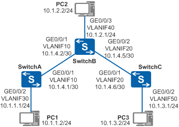
In Figure 1, PC1, PC2, and PC3 are on different network segments, and are connected through SwitchA, SwitchB, and SwitchC. Any two PCs must be connected using static routes to communicate with each other without using dynamic routing protocols.
Configuration Roadmap
The configuration roadmap is as follows:
- Create VLANs, add interfaces to VLANs, and assign IPv4 addresses to VLANIF interfaces so that neighboring devices can communicate with each other.
- Configure an IPv4 default gateway on each PC, and configure IPv4 static routes or default static routes on each Switch so that any two PCs on different network segments can communicate with each other.
Procedure
- Create VLANs and add interfaces to the VLANs.
# Configure SwitchA. The configurations of SwitchB and SwitchC are similar to the configuration of SwitchA.
<HUAWEI> system-view
[HUAWEI] sysname SwitchA
[SwitchA] vlan batch 10 30
[SwitchA] interface gigabitethernet 0/0/1
[SwitchA-GigabitEthernet0/0/1] port link-type trunk
[SwitchA-GigabitEthernet0/0/1] port trunk allow-pass vlan 10
[SwitchA-GigabitEthernet0/0/1] quit
[SwitchA] interface gigabitethernet 0/0/2
[SwitchA-GigabitEthernet0/0/2] port link-type access
[SwitchA-GigabitEthernet0/0/2] port default vlan 30
[SwitchA-GigabitEthernet0/0/2] quit
- Assign IPv4 addresses to VLANIF interfaces.
# Configure SwitchA. The configurations of SwitchB and SwitchC are similar to the configuration of SwitchA.
[SwitchA] interface vlanif 10
[SwitchA-Vlanif10] ip address 10.1.4.1 30
[SwitchA-Vlanif10] quit
[SwitchA] interface vlanif 30
[SwitchA-Vlanif30] ip address 10.1.1.1 24
[SwitchA-Vlanif30] quit
- Configure PCs.
Set the default gateway addresses of PC1, PC2, and PC3 to 10.1.1.1, 10.1.2.1, and 10.1.3.1 respectively.
- Configure IPv4 static routes.
# Configure a default IPv4 static route on SwitchA.
[SwitchA] ip route-static 0.0.0.0 0.0.0.0 10.1.4.2# Configure two IPv4 static routes on SwitchB.
[SwitchB] ip route-static 10.1.1.0 255.255.255.0 10.1.4.1
[SwitchB] ip route-static 10.1.3.0 255.255.255.0 10.1.4.6
# Configure a default IPv4 static route on SwitchC.
[SwitchC] ip route-static 0.0.0.0 0.0.0.0 10.1.4.5 - Verify the configuration.
# Check the IP routing table on SwitchA.
[SwitchA] display ip routing-table
Route Flags: R - relay, D - download to fib, T - to vpn-instance
------------------------------------------------------------------------------
Routing Tables: Public
         Destinations : 7        Routes : 7

Destination/Mask    Proto  Pre  Cost   Flags   NextHop      Interface

        0.0.0.0/0    Static 60   0        RD    10.1.4.2     Vlanif10
        10.1.1.0/24  Direct 0    0         D    10.1.1.1     Vlanif30
        10.1.1.1/32  Direct 0    0         D    127.0.0.1    Vlanif30
        10.1.4.0/30  Direct 0    0         D    10.1.4.1     Vlanif10
        10.1.4.1/32  Direct 0    0         D    127.0.0.1    Vlanif10
      127.0.0.0/8    Direct 0    0         D    127.0.0.1    InLoopBack0
      127.0.0.1/32   Direct 0    0         D    127.0.0.1    InLoopBack0
# Run the ping command to verify the connectivity.
[SwitchA] ping 10.1.3.1
  PING 10.1.3.1: 56  data bytes, press CTRL_C to break
    Reply from 10.1.3.1: bytes=56 Sequence=1 ttl=253 time=62 ms
    Reply from 10.1.3.1: bytes=56 Sequence=2 ttl=253 time=63 ms
    Reply from 10.1.3.1: bytes=56 Sequence=3 ttl=253 time=63 ms
    Reply from 10.1.3.1: bytes=56 Sequence=4 ttl=253 time=62 ms
    Reply from 10.1.3.1: bytes=56 Sequence=5 ttl=253 time=62 ms

  --- 10.1.3.1 ping statistics ---
    5 packet(s) transmitted
    5 packet(s) received
    0.00% packet loss
    round-trip min/avg/max = 62/62/63 ms
# Run the tracert command to verify the connectivity.
[SwitchA] tracert 10.1.3.1
 traceroute to  10.1.3.1(10.1.3.1), max hops: 30 ,packet length: 40,press CTRL_C to break
 1 10.1.4.2 31 ms  32 ms  31 ms
 2 10.1.3.1 62 ms  63 ms  62 ms
Configuration Files
SwitchA configuration file
#
sysname SwitchA
#
vlan batch 10 30
#
interface Vlanif10
 ip address 10.1.4.1 255.255.255.252
#
interface Vlanif30
 ip address 10.1.1.1 255.255.255.0
#
interface GigabitEthernet0/0/1
 port link-type trunk
 port trunk allow-pass vlan 10
#
interface GigabitEthernet0/0/2
 port link-type access
 port default vlan 30
#
ip route-static 0.0.0.0 0.0.0.0 10.1.4.2
#
return
SwitchB configuration file
#
sysname SwitchB
#
vlan batch 10 20 40
#
interface Vlanif10
 ip address 10.1.4.2 255.255.255.252
#
interface Vlanif20
 ip address 10.1.4.5 255.255.255.252
#
interface Vlanif40
 ip address 10.1.2.1 255.255.255.0
#
interface GigabitEthernet0/0/1
 port link-type trunk
 port trunk allow-pass vlan 10
#
interface GigabitEthernet0/0/2
 port link-type trunk
 port trunk allow-pass vlan 20
#
interface GigabitEthernet0/0/3
 port link-type access
 port default vlan 40
#
ip route-static 10.1.1.0 255.255.255.0 10.1.4.1
ip route-static 10.1.3.0 255.255.255.0 10.1.4.6
#
return
SwitchC configuration file
#
sysname SwitchC
#
vlan batch 20 50
#
interface Vlanif20
 ip address 10.1.4.6 255.255.255.252
#
interface Vlanif50
 ip address 10.1.3.1 255.255.255.0
#
interface GigabitEthernet0/0/1
 port link-type trunk
 port trunk allow-pass vlan 20
#
interface GigabitEthernet0/0/2
 port link-type access
 port default vlan 50
#
ip route-static 0.0.0.0 0.0.0.0 10.1.4.5
#
return