Example for Configuring Static BFD for IPv4 Static Routes
Networking Requirements
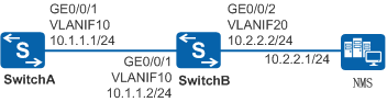
In Figure 1, SwitchA connects to the network management system (NMS) across a network segment through SwitchB. Static routes need to be configured on SwitchA so that SwitchA can communicate with the NMS. Link fault detection between SwitchA and SwitchB must be completed within a few milliseconds to speed up route convergence.
Configuration Roadmap
The configuration roadmap is as follows:
Configure a BFD session between SwitchA and SwitchB to complete link fault detection within a few milliseconds.
Configure a static route from SwitchA to the NMS and bind a BFD session to the static route to complete link fault detection within a few milliseconds and speed up route convergence.
Procedure
- Create VLANs and add interfaces to the VLANs.
# Configure SwitchA. The configurations of SwitchB are similar to the configuration of SwitchA.
<HUAWEI> system-view
[HUAWEI] sysname SwitchA
[SwitchA] vlan 10
[SwitchA-vlan10] quit
[SwitchA] interface gigabitethernet 0/0/1
[SwitchA-GigabitEthernet0/0/1] port link-type trunk
[SwitchA-GigabitEthernet0/0/1] port trunk allow-pass vlan 10
[SwitchA-GigabitEthernet0/0/1] quit
- Assign IP addresses to VLANIF interfaces.
# Configure SwitchA. The configurations of SwitchB are similar to the configuration of SwitchA.
[SwitchA] interface vlanif 10
[SwitchA-Vlanif10] ip address 10.1.1.1 24
[SwitchA-Vlanif10] quit
- Configure a BFD session between SwitchA and SwitchB.
# Create a BFD session on SwitchA.
[SwitchA] bfd
[SwitchA-bfd] quit
[SwitchA] bfd aa bind peer-ip 10.1.1.2
[SwitchA-bfd-session-aa] discriminator local 10
[SwitchA-bfd-session-aa] discriminator remote 20
[SwitchA-bfd-session-aa] commit
[SwitchA-bfd-session-aa] quit
# Create a BFD session on SwitchB.
[SwitchB] bfd
[SwitchB-bfd] quit
[SwitchB] bfd bb bind peer-ip 10.1.1.1
[SwitchB-bfd-session-bb] discriminator local 20
[SwitchB-bfd-session-bb] discriminator remote 10
[SwitchB-bfd-session-bb] commit
[SwitchB-bfd-session-bb] quit
- Configure a static route and bind it to the BFD session.
# On SwitchA, configure a default static route to the external network and bind it to the BFD session named aa.
[SwitchA]ip route-static 10.2.2.0 24 10.1.1.2 track bfd-session aa - Verify the configuration.
# After the configuration is complete, run the display bfd session all command on SwitchA and SwitchB. The command output shows that the BFD session has been established and is Up.
The display on SwitchA is used as an example.
[SwitchA] display bfd session all
--------------------------------------------------------------------------------
Local Remote PeerIpAddr      State     Type        InterfaceName
--------------------------------------------------------------------------------
10    20     10.1.1.2        Up        S_IP_PEER         -
--------------------------------------------------------------------------------
     Total UP/DOWN Session Number : 1/0
# Check the IP routing table on SwitchA. The command output shows that the static route 10.2.2.0/24 exists in the routing table.
[SwitchA] display ip routing-table
Route Flags: R - relay, D - download to fib, T - to vpn-instance
------------------------------------------------------------------------------
Routing Tables: Public
         Destinations : 5        Routes : 5

Destination/Mask    Proto   Pre  Cost    Flags NextHop       Interface

        10.1.1.0/24  Direct  0    0          D   10.1.1.1      Vlanif10
        10.1.1.1/32  Direct  0    0          D   127.0.0.1     Vlanif10
        10.2.2.0/24  Static  60   0         RD   10.1.1.2      Vlanif10
      127.0.0.0/8    Direct  0    0          D   127.0.0.1     InLoopBack0
      127.0.0.1/32   Direct  0    0          D   127.0.0.1     InLoopBack0
# Run the shutdown command on GE 0/0/1 of SwitchB to simulate a link fault.
[SwitchB] interface gigabitethernet 0/0/1
[SwitchB-GigabitEthernet0/0/1] shutdown
# Check the IP routing table on SwitchA. The command output shows that the static route 10.2.2.0/24 does not exist. This is because the static route has been bound to a BFD session, and BFD immediately notifies that the bound static route becomes unavailable after detecting a link fault.
[SwitchA]display ip routing-table
Route Flags: R - relay, D - download to fib, T - to vpn-instance
------------------------------------------------------------------------------
Routing Tables: Public
         Destinations : 2        Routes : 2

Destination/Mask    Proto   Pre  Cost    Flags NextHop       Interface

      127.0.0.0/8   Direct  0    0          D  127.0.0.1     InLoopBack0
      127.0.0.1/32  Direct  0    0          D  127.0.0.1     InLoopBack0
# Run the undo shutdown command on GE0/0/1 of SwitchB to simulate link recovery.
[SwitchB-GigabitEthernet0/0/1]undo shutdown
# Check the IP routing table on SwitchA. The command output shows that the static route 10.2.2.0/24 exists in the routing table. This is because BFD immediately notifies that the bound static route becomes reachable again after detecting link recovery.
[SwitchA] display ip routing-table
Route Flags: R - relay, D - download to fib, T - to vpn-instance
------------------------------------------------------------------------------
Routing Tables: Public
         Destinations : 5        Routes : 5

Destination/Mask    Proto   Pre  Cost    Flags NextHop       Interface

        10.1.1.0/24  Direct  0    0          D   10.1.1.1      Vlanif10
        10.1.1.1/32  Direct  0    0          D   127.0.0.1     Vlanif10
        10.2.2.0/24  Static  60   0         RD   10.1.1.2      Vlanif10
      127.0.0.0/8    Direct  0    0          D   127.0.0.1     InLoopBack0
      127.0.0.1/32   Direct  0    0          D   127.0.0.1     InLoopBack0
Configuration Files
SwitchA configuration file
#
sysname SwitchA
#
vlan batch 10
#
bfd
#
interface Vlanif10
 ip address 10.1.1.1 255.255.255.0
#
interface GigabitEthernet0/0/1
 port link-type trunk
 port trunk allow-pass vlan 10
#
bfd aa bind peer-ip 10.1.1.2
 discriminator local 10
 discriminator remote 20
 commit
#
ip route-static 10.2.2.0 255.255.255.0 10.1.1.2 track bfd-session aa
#
return
SwitchB configuration file
#
sysname SwitchB
#
vlan batch 10 20
#
bfd
#
interface Vlanif10
 ip address 10.1.1.2 255.255.255.0
#
interface Vlanif20
 ip address 10.2.2.2 255.255.255.0
#
interface GigabitEthernet0/0/1
 port link-type trunk
 port trunk allow-pass vlan 10
#
interface GigabitEthernet0/0/2
 port link-type trunk
 port trunk allow-pass vlan 20
#
bfd bb bind peer-ip 10.1.1.1
 discriminator local 20
 discriminator remote 10
 commit
#
return