Example for Configuring STP
Networking Requirements
On a complex network, multiple physical links are often deployed between two devices for link redundancy (one as the active link and the others as standby links). However, redundant links may cause loops on the network, which result in broadcast storms and unstable MAC address entries.
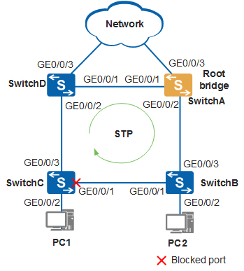
STP can be deployed on a network to eliminate loops by blocking ports. In Figure 1, a loop exists on the network, and SwitchA, SwitchB, SwitchC, and SwitchD are all running STP. These devices exchange STP BPDUs to discover loops and block some ports to prune the network into a loop-free tree network, improving packet processing performance.
Configuration Roadmap
- Configure the STP mode for the switches on the ring network.
- Configure the root bridge and secondary root bridge.
- Set a path cost for the ports to be blocked.
- Enable STP to eliminate loops. Because ports connected to the PCs do not participate in STP calculation, configure both of these ports as edge ports.
Procedure
- Configure basic STP functions.
Configure the STP mode for the switches on the ring network.
# Configure the STP mode on SwitchA.
<HUAWEI> system-view
[HUAWEI] sysname SwitchA
[SwitchA] stp mode stp
# Configure the STP mode on SwitchB.
<HUAWEI> system-view
[HUAWEI] sysname SwitchB
[SwitchB] stp mode stp
# Configure the STP mode on SwitchC.
<HUAWEI> system-view
[HUAWEI] sysname SwitchC
[SwitchC] stp mode stp
# Configure the STP mode on SwitchD.
<HUAWEI> system-view
[HUAWEI] sysname SwitchD
[SwitchD] stp mode stp
Configure the root bridge and secondary root bridge.
# Configure SwitchA as the root bridge.
[SwitchA] stp root primary
# Configure SwitchD as the secondary root bridge.
[SwitchD] stp root secondary
Set a path cost for the ports to be blocked.
The path cost value range depends on path cost calculation methods, which must be the same on all switches. This example uses the Huawei proprietary calculation method.
# On Switch A, set the path cost calculation method to the Huawei proprietary method.
[SwitchA] stp pathcost-standard legacy
# On SwitchB, set the path cost calculation method to the Huawei proprietary method.
[SwitchB] stp pathcost-standard legacy
# On Switch C, set the path cost of GigabitEthernet0/0/1 to 20000.
[SwitchC] stp pathcost-standard legacy
[SwitchC] interface gigabitethernet 0/0/1
[SwitchC-GigabitEthernet0/0/1] stp cost 20000
[SwitchC-GigabitEthernet0/0/1] quit
# On SwitchD, set the path cost calculation method to the Huawei proprietary method.
[SwitchD] stp pathcost-standard legacy
Enable STP to eliminate loops.
Configure the ports connected to PCs both as edge ports.
# Configure GigabitEthernet0/0/2 on SwitchB as an edge port.
[SwitchB] interface gigabitethernet 0/0/2
[SwitchB-GigabitEthernet0/0/2] stp edged-port enable
[SwitchB-GigabitEthernet0/0/2] quit
(Optional) Configure BPDU protection on SwitchB.
[SwitchB] stp bpdu-protection
# Configure GigabitEthernet0/0/2 on SwitchC as an edge port.
[SwitchC] interface gigabitethernet 0/0/2
[SwitchC-GigabitEthernet0/0/2] stp edged-port enable
[SwitchC-GigabitEthernet0/0/2] quit
(Optional) Configure BPDU protection on SwitchC.
[SwitchC] stp bpdu-protection

If edge ports are connected to network devices that have STP enabled and BPDU protection is enabled, the edge ports will be shut down and their attributes remain unchanged after they receive BPDUs.
Enable STP globally.
# Enable STP globally on SwitchA.
[SwitchA] stp enable# Enable STP globally on SwitchB.
[SwitchB] stp enable# Enable STP globally on SwitchC.
[SwitchC] stp enable# Enable STP globally on SwitchD.
[SwitchD] stp enable
- Verify the configuration.
After the preceding configuration is complete and the network becomes stable, perform the following operations to verify the configuration:
# Run the display stp brief command on SwitchA to check the port states and protection type.
[SwitchA] display stp brief
 MSTID  Port                        Role  STP State     Protection
   0    GigabitEthernet0/0/1        DESI  FORWARDING      NONE
   0    GigabitEthernet0/0/2        DESI  FORWARDING      NONE
After SwitchA is configured as the root bridge, GigabitEthernet0/0/2 connected to SwitchB and GigabitEthernet0/0/1 connected to SwitchD are elected as designated ports through spanning tree calculation.
# Run the display stp interface gigabitethernet 0/0/1 brief command on SwitchB to check the status of GigabitEthernet0/0/1.
[SwitchB] display stp interface gigabitethernet 0/0/1 brief
 MSTID  Port                        Role  STP State     Protection
   0    GigabitEthernet0/0/1        DESI  FORWARDING      NONE
GigabitEthernet0/0/1 is elected as a designated port and is in Forwarding state.
# Run the display stp brief command on SwitchC to check the port states and protection type.
[SwitchC] display stp brief
 MSTID  Port                        Role  STP State     Protection
   0    GigabitEthernet0/0/1        ALTE  DISCARDING      NONE
   0    GigabitEthernet0/0/3        ROOT  FORWARDING      NONE
GigabitEthernet0/0/3 is elected as a root port and is in Forwarding state.
GigabitEthernet0/0/1 is elected as an alternate port and is in Discarding state.
Configuration Files
SwitchA configuration file
#
sysname SwitchA
#
stp mode stp
stp instance 0 root primary
stp pathcost-standard legacy
#
return
SwitchB configuration file
#
sysname SwitchB
#
stp mode stp
stp bpdu-protection
stp pathcost-standard legacy
#
interface GigabitEthernet0/0/2
 stp edged-port enable
#
return
SwitchC configuration file
#
sysname SwitchC
#
stp mode stp
stp pathcost-standard legacy
stp bpdu-protection
#
interface GigabitEthernet0/0/1
 stp instance 0 cost 20000
#
interface GigabitEthernet0/0/2
 stp edged-port enable
#
return
SwitchD configuration file
#
sysname SwitchD
#
stp mode stp
stp instance 0 root secondary
stp pathcost-standard legacy
#
return