Example for Configuring MSTP Multi-Process for Layer 2 Single-Access Rings and Layer 2 Multi-Access Rings
Networking Requirements
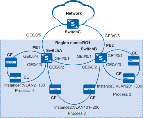
On a network deployed with both Layer 2 single-access rings and multi-access rings, switches transmit both Layer 2 and Layer 3 services. To enable different rings to transmit different services, configure MSTP multi-process. Spanning trees of different processes are calculated independently.
In Figure 1, both Layer 2 single-access rings and dual-access rings are deployed and switches A and B carry both Layer 2 and Layer 3 services. Switches A and B connected to dual-access rings are also connected to a single-access ring.

Configuration Roadmap
The configuration roadmap is as follows:
Configure basic MSTP functions, add a device to an MST region, and create MSTIs.
Each ring can belong to only one region.
Each CE can join only one ring.
Configure multiple MSTP processes:
Create multiple MSTP processes and add interfaces to these processes.
Configure a shared link.
Configure MSTP protection functions:
Configure priorities of MSTP processes and enable root protection.
Configure shared link protection.
Configure the Layer 2 forwarding function on devices.
Procedure
- Configure basic MSTP functions, add devices to an MST region,
and create MSTIs.
Configure MST regions and create MSTIs.
# Configure an MST region and create MSTIs on SwitchA.
<HUAWEI> system-view[HUAWEI] sysname SwitchA[SwitchA] stp region-configuration
[SwitchA-mst-region] region-name RG1
[SwitchA-mst-region] instance 1 vlan 2 to 100
[SwitchA-mst-region] instance 2 vlan 101 to 200
[SwitchA-mst-region] instance 3 vlan 201 to 300
[SwitchA-mst-region] active region-configuration
[SwitchA-mst-region] quit
# Configure an MST region and create MSTIs on SwitchB.
<HUAWEI> system-view[HUAWEI] sysname SwitchB[SwitchB] stp region-configuration
[SwitchB-mst-region] region-name RG1
[SwitchB-mst-region] instance 1 vlan 2 to 100
[SwitchB-mst-region] instance 2 vlan 101 to 200
[SwitchB-mst-region] instance 3 vlan 201 to 300
[SwitchB-mst-region] active region-configuration
[SwitchB-mst-region] quit
Enable MSTP.
# Configure SwitchA.
[SwitchA] stp enable
# Configure SwitchB.
[SwitchB] stp enable
- Configure multiple MSTP processes.
Create multiple MSTP processes and add interfaces to these processes.
# Create MSTP processes 1 and 2 on SwitchA.
[SwitchA] stp process 1
[SwitchA-mst-process-1] quit
[SwitchA] stp process 2
[SwitchA-mst-process-2] quit
# Create MSTP processes 2 and 3 on SwitchB.
[SwitchB] stp process 2
[SwitchB-mst-process-2] quit
[SwitchB] stp process 3
[SwitchB-mst-process-3] quit
# Add GE 0/0/3 and GE 0/0/4 on SwitchA to MSTP process 1 and GE 0/0/2 to MSTP process 2.
[SwitchA] interface gigabitethernet 0/0/4[SwitchA-GigabitEthernet0/0/4] stp enable[SwitchA-GigabitEthernet0/0/4] bpdu enable[SwitchA-GigabitEthernet0/0/4] stp binding process 1[SwitchA-GigabitEthernet0/0/4] quit[SwitchA] interface gigabitethernet 0/0/3[SwitchA-GigabitEthernet0/0/3] stp enable[SwitchA-GigabitEthernet0/0/3] bpdu enable[SwitchA-GigabitEthernet0/0/3] stp binding process 1[SwitchA-GigabitEthernet0/0/3] quit[SwitchA] interface gigabitethernet 0/0/2[SwitchA-GigabitEthernet0/0/2] stp enable[SwitchA-GigabitEthernet0/0/2] bpdu enable[SwitchA-GigabitEthernet0/0/2] stp binding process 2[SwitchA-GigabitEthernet0/0/2] quit# Add GE 0/0/3 and GE 0/0/4 on SwitchB to MSTP process 3 and GE 0/0/2 to MSTP process 2.
[SwitchB] interface gigabitethernet 0/0/4[SwitchB-GigabitEthernet0/0/4] stp enable[SwitchB-GigabitEthernet0/0/4] bpdu enable[SwitchB-GigabitEthernet0/0/4] stp binding process 3[SwitchB-GigabitEthernet0/0/4] quit[SwitchB] interface gigabitethernet 0/0/3[SwitchB-GigabitEthernet0/0/3] stp enable[SwitchB-GigabitEthernet0/0/3] bpdu enable[SwitchB-GigabitEthernet0/0/3] stp binding process 3[SwitchB-GigabitEthernet0/0/3] quit[SwitchB] interface gigabitethernet 0/0/2[SwitchB-GigabitEthernet0/0/2] stp enable[SwitchB-GigabitEthernet0/0/2] bpdu enable[SwitchB-GigabitEthernet0/0/2] stp binding process 2[SwitchB-GigabitEthernet0/0/2] quitConfigure a shared link.
# Configure SwitchA.
[SwitchA] interface gigabitethernet 0/0/1[SwitchA-GigabitEthernet0/0/1] stp enable[SwitchA-GigabitEthernet0/0/1] bpdu enable[SwitchA-GigabitEthernet0/0/1] stp binding process 2 link-share[SwitchA-GigabitEthernet0/0/1] quit# Configure SwitchB.
[SwitchB] interface gigabitethernet 0/0/1[SwitchB-GigabitEthernet0/0/1] stp enable[SwitchB-GigabitEthernet0/0/1] bpdu enable[SwitchB-GigabitEthernet0/0/1] stp binding process 2 link-share[SwitchB-GigabitEthernet0/0/1] quitEnable the MSTP function in MSTP multi-process.
# Configure SwitchA.
[SwitchA] stp process 1
[SwitchA-mst-process-1] stp enable
[SwitchA-mst-process-1] quit
[SwitchA] stp process 2
[SwitchA-mst-process-2] stp enable
[SwitchA-mst-process-2] quit
# Configure SwitchB.
[SwitchB] stp process 3
[SwitchB-mst-process-3] stp enable
[SwitchB-mst-process-3] quit
[SwitchB] stp process 2
[SwitchB-mst-process-2] stp enable
[SwitchB-mst-process-2] quit
- Configure MSTP protection functions.
Configure priorities of MSTP processes and enable root protection.
# Configure SwitchA.
[SwitchA] stp process 1
[SwitchA-mst-process-1] stp instance 0 root primary
[SwitchA-mst-process-1] stp instance 1 root primary
[SwitchA-mst-process-1] quit
[SwitchA] stp process 2
[SwitchA-mst-process-2] stp instance 0 root primary
[SwitchA-mst-process-2] stp instance 2 root primary
[SwitchA-mst-process-2] quit
[SwitchA] interface gigabitethernet 0/0/2[SwitchA-GigabitEthernet0/0/2] stp root-protection[SwitchA-GigabitEthernet0/0/2] quit# Configure SwitchB.
[SwitchB] stp process 3
[SwitchB-mst-process-3] stp instance 0 root primary
[SwitchB-mst-process-3] stp instance 3 root primary
[SwitchB-mst-process-3] quit
[SwitchB] stp process 2
[SwitchB-mst-process-2] stp instance 0 root secondary
[SwitchB-mst-process-2] stp instance 2 root secondary
[SwitchB-mst-process-2] quit
[SwitchB] interface gigabitethernet 0/0/2[SwitchB-GigabitEthernet0/0/2] stp root-protection[SwitchB-GigabitEthernet0/0/2] quit In each ring, the priority of the MSTP process on the downstream CE must be lower than the priority of the MSTP process on the switch.
For switches A and B on the dual-access ring, you are recommended to configure them as the primary root bridges of different MSTIs.
Configure shared link protection.
# Configure SwitchA.
[SwitchA] stp process 2
[SwitchA-mst-process-2] stp link-share-protection
[SwitchA-mst-process-2] quit
# Configure SwitchB.
[SwitchB] stp process 2
[SwitchB-mst-process-2] stp link-share-protection
[SwitchB-mst-process-2] quit
- Create VLANs and add interfaces to VLANs.
# Create VLANs 2 to 200 on SwitchA. Add GE 0/0/3 and GE 0/0/4 to VLANs 2 to 100, and add GE 0/0/1 and GE 0/0/2 to VLANs 101 to 200.
[SwitchA] vlan batch 2 to 200
[SwitchA] interface gigabitethernet 0/0/3[SwitchA-GigabitEthernet0/0/3] port link-type trunk[SwitchA-GigabitEthernet0/0/3] port trunk allow-pass vlan 2 to 100[SwitchA-GigabitEthernet0/0/3] quit[SwitchA] interface gigabitethernet 0/0/4[SwitchA-GigabitEthernet0/0/4] port link-type trunk[SwitchA-GigabitEthernet0/0/4] port trunk allow-pass vlan 2 to 100[SwitchA-GigabitEthernet0/0/4] quit[SwitchA] interface gigabitethernet 0/0/1[SwitchA-GigabitEthernet0/0/1] port link-type trunk[SwitchA-GigabitEthernet0/0/1] port trunk allow-pass vlan 101 to 200[SwitchA-GigabitEthernet0/0/1] quit[SwitchA] interface gigabitethernet 0/0/2[SwitchA-GigabitEthernet0/0/2] port link-type trunk[SwitchA-GigabitEthernet0/0/2] port trunk allow-pass vlan 101 to 200[SwitchA-GigabitEthernet0/0/2] quit# Create VLANs 101 to 300 on SwitchB. Add GE 0/0/3 and GE 0/0/4 to VLANs 201 to 300, and add GE 0/0/1 and GE 0/0/2 to VLANs 101 to 200.
[SwitchB] vlan batch 101 to 300
[SwitchB] interface gigabitethernet 0/0/3[SwitchB-GigabitEthernet0/0/3] port link-type trunk[SwitchB-GigabitEthernet0/0/3] port trunk allow-pass vlan 201 to 300[SwitchB-GigabitEthernet0/0/3] quit[SwitchB] interface gigabitethernet 0/0/4[SwitchB-GigabitEthernet0/0/4] port link-type trunk[SwitchB-GigabitEthernet0/0/4] port trunk allow-pass vlan 201 to 300[SwitchB-GigabitEthernet0/0/4] quit[SwitchB] interface gigabitethernet 0/0/1[SwitchB-GigabitEthernet0/0/1] port link-type trunk[SwitchB-GigabitEthernet0/0/1] port trunk allow-pass vlan 101 to 200[SwitchB-GigabitEthernet0/0/1] quit[SwitchB] interface gigabitethernet 0/0/2[SwitchB-GigabitEthernet0/0/2] port link-type trunk[SwitchB-GigabitEthernet0/0/2] port trunk allow-pass vlan 101 to 200[SwitchB-GigabitEthernet0/0/2] quit - Verify the configuration.
Run the display stp interface brief command on SwitchA.
# GE 0/0/4 is a designated port in the CIST of MSTP process 1 and in MSTI 1.
[SwitchA] display stp process 1 interface gigabitethernet 0/0/4 brief
MSTID Port Role STP State Protection
   0        GigabitEthernet0/0/4          DESI  FORWARDING      NONE
   1        GigabitEthernet0/0/4          DESI  FORWARDING      NONE
# GE 0/0/2 is a designated port in the CIST of MSTP process 2 and in MSTI 2.
[SwitchA] display stp process 2 interface gigabitethernet 0/0/2 brief
MSTID Port Role STP State Protection
   0        GigabitEthernet0/0/2          DESI  FORWARDING      ROOT
   2        GigabitEthernet0/0/2          DESI  FORWARDING      ROOT
Run the display stp interface brief command on SwitchB.
# GE 0/0/4 is a designated port in the CIST of MSTP process 3 and in MSTI 3.
[SwitchB] display stp process 3 interface gigabitethernet 0/0/4 brief
MSTID Port Role STP State Protection
   0        GigabitEthernet0/0/4          DESI  FORWARDING      NONE
   3        GigabitEthernet0/0/4          DESI  FORWARDING      NONE
# GE 0/0/2 is a designated port in the CIST of MSTP process 2 and in MSTI 2.
[SwitchB] display stp process 2 interface gigabitethernet 0/0/2 brief
MSTID Port Role STP State Protection
   0        GigabitEthernet0/0/2          DESI  FORWARDING      ROOT
   2        GigabitEthernet0/0/2          DESI  FORWARDING      ROOT
Configuration Files
Only the MSTP-related configuration files are provided.
SwitchA configuration file
#
 sysname SwitchA
#
 vlan batch 2 to 200
#
 stp region-configuration
  region-name RG1
  instance 1 vlan 2 to 100
  instance 2 vlan 101 to 200
  instance 3 vlan 201 to 300
  active region-configuration
#
stp process 1
 stp instance 0 root primary
 stp instance 1 root primary
 stp enable
stp process 2
 stp instance 0 root primary
 stp instance 2 root primary
 stp link-share-protection
 stp enable
#
interface GigabitEthernet0/0/1
 port link-type trunk
 port trunk allow-pass vlan 101 to 200
 stp binding process 2 link-share
#
interface GigabitEthernet0/0/2
 port link-type trunk
 port trunk allow-pass vlan 101 to 200
 stp binding process 2
 stp root-protection
#
interface GigabitEthernet0/0/3
 port link-type trunk
 port trunk allow-pass vlan 2 to 100
 stp binding process 1
#
interface GigabitEthernet0/0/4
 port link-type trunk
 port trunk allow-pass vlan 2 to 100
 stp binding process 1
#
return
SwitchB configuration file
#
 sysname SwitchB
#
 vlan batch 101 to 300
#
 stp region-configuration
  region-name RG1
  instance 1 vlan 2 to 100
  instance 2 vlan 101 to 200
  instance 3 vlan 201 to 300
  active region-configuration
#
stp process 2
 stp instance 0 root secondary
 stp instance 2 root secondary
 stp link-share-protection
 stp enable
stp process 3
 stp instance 0 root primary
 stp instance 3 root primary
 stp enable
#
interface GigabitEthernet0/0/1
 port link-type trunk
 port trunk allow-pass vlan 101 to 200
 stp binding process 2 link-share
#
interface GigabitEthernet0/0/2
 port link-type trunk
 port trunk allow-pass vlan 101 to 200
 stp binding process 2
 stp root-protection
#
interface GigabitEthernet0/0/3
 port link-type trunk
 port trunk allow-pass vlan 201 to 300
 stp binding process 3
#
interface GigabitEthernet0/0/4
 port link-type trunk
 port trunk allow-pass vlan 201 to 300
 stp binding process 3
#
return