Example for Configuring MSTP
Networking Requirements
To implement redundancy on a complex network, network designers tend to deploy multiple physical links between two devices, one of which is the master and the others are the backup. Loops occur, causing broadcast storms or damaging MAC addresses. After the network is planned, deploy MSTP on the network to prevent loops. MSTP blocks redundant links and prunes a network into a tree topology free from loops.
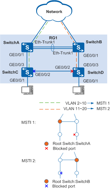
As shown in Figure 1, SwitchA, SwitchB, SwitchC, and SwitchD run MSTP. To load balance traffic from VLANs 2 to 10 and VLANs 11 to 20, use MSTP multi-instance. You can configure a VLAN mapping table to associate VLANs with MSTIs.
Configuration Roadmap
The configuration roadmap is as follows:
Configure basic MSTP functions on the switch on the ring network. Because ports connected to the PCs do not participate in MSTP calculation, configure these ports as edge ports.
Configure protection functions to protect devices or links. You can configure root protection on the designated port of the root bridge.

When the link between the root bridge and secondary root bridge goes Down, the port enabled with root protection becomes Discarding because root protection takes effect.
To improve the reliability, you are advised to bind the link between the root bridge and secondary root bridge to an Eth-Trunk.
Configure Layer 2 forwarding.
Procedure
- Configure basic MSTP functions.
Configure SwitchA, SwitchB, SwitchC, and SwitchD in the same MST region named RG1 and create MSTI 1 and MSTI 2.
# Configure an MST region on SwitchA.
<HUAWEI> system-view
[HUAWEI] sysname SwitchA
[SwitchA] stp region-configuration
[SwitchA-mst-region] region-name RG1
[SwitchA-mst-region] instance 1 vlan 2 to 10
[SwitchA-mst-region] instance 2 vlan 11 to 20
[SwitchA-mst-region] active region-configuration
[SwitchA-mst-region] quit
# Configure an MST region on SwitchB.
<HUAWEI> system-view
[HUAWEI] sysname SwitchB
[SwitchB] stp region-configuration
[SwitchB-mst-region] region-name RG1
[SwitchB-mst-region] instance 1 vlan 2 to 10
[SwitchB-mst-region] instance 2 vlan 11 to 20
[SwitchB-mst-region] active region-configuration
[SwitchB-mst-region] quit
# Configure an MST region on SwitchC.
<HUAWEI> system-view
[HUAWEI] sysname SwitchC
[SwitchC] stp region-configuration
[SwitchC-mst-region] region-name RG1
[SwitchC-mst-region] instance 1 vlan 2 to 10
[SwitchC-mst-region] instance 2 vlan 11 to 20
[SwitchC-mst-region] active region-configuration
[SwitchC-mst-region] quit
# Configure an MST region on SwitchD.
<HUAWEI> system-view
[HUAWEI] sysname SwitchD
[SwitchD] stp region-configuration
[SwitchD-mst-region] region-name RG1
[SwitchD-mst-region] instance 1 vlan 2 to 10
[SwitchD-mst-region] instance 2 vlan 11 to 20
[SwitchD-mst-region] active region-configuration
[SwitchD-mst-region] quit
In the MST region RG1, configure the root bridge and secondary root bridge in MSTI 1 and MSTI 2.
Configure the root bridge and secondary root bridge in MSTI 1.
# Configure SwitchA as the root bridge in MSTI 1.
[SwitchA] stp instance 1 root primary
# Configure SwitchB as the secondary root bridge in MSTI 1.
[SwitchB] stp instance 1 root secondary
Configure the root bridge and secondary root bridge in MSTI 2.
# Configure SwitchB as the root bridge in MSTI 2.
[SwitchB] stp instance 2 root primary
# Configure SwitchA as the secondary root bridge in MSTI 2.
[SwitchA] stp instance 2 root secondary
Set the path costs of the ports to be blocked in MSTI 1 and MSTI 2 to be greater than the default value.
The path cost values depend on path cost calculation methods. This example uses the Huawei calculation method as an example to set the path cost to 20000 for the ports to be blocked.
All switches on a network must use the same path cost calculation method.
# Configure SwitchA to use Huawei calculation method to calculate the path cost.
[SwitchA] stp pathcost-standard legacy
# Configure SwitchB to use Huawei calculation method to calculate the path cost.
[SwitchB] stp pathcost-standard legacy
# Configure SwitchC to use Huawei calculation method to calculate the path cost, and set the path cost of GE0/0/2 in MSTI 2 to 20000.
[SwitchC] stp pathcost-standard legacy
[SwitchC] interface gigabitethernet 0/0/2
[SwitchC-GigabitEthernet0/0/2] stp instance 2 cost 20000
[SwitchC-GigabitEthernet0/0/2] quit
# Configure SwitchD to use Huawei calculation method to calculate the path cost, and set the path cost of GE0/0/2 in MSTI 1 to 20000.
[SwitchD] stp pathcost-standard legacy
[SwitchD] interface gigabitethernet 0/0/2
[SwitchD-GigabitEthernet0/0/2] stp instance 1 cost 20000
[SwitchD-GigabitEthernet0/0/2] quit
Enable MSTP to eliminate loops.
Enable MSTP globally.
# Enable MSTP on SwitchA.
[SwitchA] stp enable
# Enable MSTP on SwitchB.
[SwitchB] stp enable
# Enable MSTP on SwitchC.
[SwitchC] stp enable
# Enable MSTP on SwitchD.
[SwitchD] stp enable
Configure the ports connected to the terminal as edge ports.
# Configure GE0/0/1 of SwitchC as an edge port.
[SwitchC] interface gigabitethernet 0/0/1
[SwitchC-GigabitEthernet0/0/1] stp edged-port enable
[SwitchC-GigabitEthernet0/0/1] quit
(Optional) Configure BPDU protection on SwitchC.
[SwitchC] stp bpdu-protection
# Configure GE0/0/1 of SwitchD as an edge port.
[SwitchD] interface gigabitethernet 0/0/1
[SwitchD-GigabitEthernet0/0/1] stp edged-port enable
[SwitchD-GigabitEthernet0/0/1] quit
(Optional) Configure BPDU protection on SwitchD.
[SwitchD] stp bpdu-protection
If edge ports are connected to network devices that have STP enabled and BPDU protection is enabled, the edge ports will be shut down and their attributes remain unchanged after they receive BPDUs.
- Configure root protection on the designated port of the
root bridge.
# Enable root protection on GE0/0/1 of SwitchA.
[SwitchA] interface gigabitethernet 0/0/1
[SwitchA-GigabitEthernet0/0/1] stp root-protection
[SwitchA-GigabitEthernet0/0/1] quit
# Enable root protection on GE0/0/1 of SwitchB.
[SwitchB] interface gigabitethernet 0/0/1
[SwitchB-GigabitEthernet0/0/1] stp root-protection
[SwitchB-GigabitEthernet0/0/1] quit
- Configure Layer 2 forwarding on devices on the ring network.
Create VLANs 2 to 20 on SwitchA, SwitchB, SwitchC, and SwitchD.
# Create VLANs 2 to 20 on SwitchA.
[SwitchA] vlan batch 2 to 20
# Create VLANs 2 to 20 on SwitchB.
[SwitchB] vlan batch 2 to 20
# Create VLANs 2 to 20 on SwitchC.
[SwitchC] vlan batch 2 to 20
# Create VLANs 2 to 20 on SwitchD.
[SwitchD] vlan batch 2 to 20
Add ports on switches to VLANs.
# Add GE0/0/1 on SwitchA to a VLAN.
[SwitchA] interface gigabitethernet 0/0/1
[SwitchA-GigabitEthernet0/0/1] port link-type trunk
[SwitchA-GigabitEthernet0/0/1] port trunk allow-pass vlan 2 to 20
[SwitchA-GigabitEthernet0/0/1] quit
# Add Eth-Trunk1 on SwitchA to a VLAN.
[SwitchA] interface Eth-Trunk 1
[SwitchA-Eth-Trunk1] trunkport gigabitethernet 0/0/2
[SwitchA-Eth-Trunk1] trunkport gigabitethernet 0/0/3
[SwitchA-Eth-Trunk1] port link-type trunk
[SwitchA-Eth-Trunk1] port trunk allow-pass vlan 2 to 20
[SwitchA-Eth-Trunk1] quit
# Add GE0/0/1 on SwitchB to a VLAN.
[SwitchB] interface gigabitethernet 0/0/1
[SwitchB-GigabitEthernet0/0/1] port link-type trunk
[SwitchB-GigabitEthernet0/0/1] port trunk allow-pass vlan 2 to 20
[SwitchB-GigabitEthernet0/0/1] quit
# Add Eth-Trunk1 on SwitchB to a VLAN.
[SwitchB] interface Eth-Trunk 1
[SwitchB-Eth-Trunk1] trunkport gigabitethernet 0/0/2
[SwitchB-Eth-Trunk1] trunkport gigabitethernet 0/0/3
[SwitchB-Eth-Trunk1] port link-type trunk
[SwitchB-Eth-Trunk1] port trunk allow-pass vlan 2 to 20
[SwitchB-Eth-Trunk1] quit
# Add GE0/0/1 on SwitchC to a VLAN.
[SwitchC] interface gigabitethernet 0/0/1
[SwitchC-GigabitEthernet0/0/1] port link-type access
[SwitchC-GigabitEthernet0/0/1] port default vlan 2
[SwitchC-GigabitEthernet0/0/1] quit
# Add GE0/0/2 on SwitchC to a VLAN.
[SwitchC] interface gigabitethernet 0/0/2
[SwitchC-GigabitEthernet0/0/2] port link-type trunk
[SwitchC-GigabitEthernet0/0/2] port trunk allow-pass vlan 2 to 20
[SwitchC-GigabitEthernet0/0/2] quit
# Add GE0/0/3 on SwitchC to a VLAN.
[SwitchC] interface gigabitethernet 0/0/3
[SwitchC-GigabitEthernet0/0/3] port link-type trunk
[SwitchC-GigabitEthernet0/0/3] port trunk allow-pass vlan 2 to 20
[SwitchC-GigabitEthernet0/0/3] quit
# Add GE0/0/1 on SwitchD to a VLAN.
[SwitchD] interface gigabitethernet 0/0/1
[SwitchD-GigabitEthernet0/0/1] port link-type access
[SwitchD-GigabitEthernet0/0/1] port default vlan 11
[SwitchD-GigabitEthernet0/0/1] quit
# Add GE0/0/2 on SwitchD to a VLAN.
[SwitchD] interface gigabitethernet 0/0/2
[SwitchD-GigabitEthernet0/0/2] port link-type trunk
[SwitchD-GigabitEthernet0/0/2] port trunk allow-pass vlan 2 to 20
[SwitchD-GigabitEthernet0/0/2] quit
# Add GE0/0/3 on SwitchD to a VLAN.
[SwitchD] interface gigabitethernet 0/0/3
[SwitchD-GigabitEthernet0/0/3] port link-type trunk
[SwitchD-GigabitEthernet0/0/3] port trunk allow-pass vlan 2 to 20
[SwitchD-GigabitEthernet0/0/3] quit
- Verify the configuration.
After the preceding configurations are complete and the network topology becomes stable, perform the following operations to verify the configuration.
MSTI 1 and MSTI 2 are used as examples. You do not need to check the interface status in MSTI 0.
# Run the display stp brief command on SwitchA to view the status and protection mode on the ports. Output similar to the following is displayed:
[SwitchA] display stp brief
 MSTID  Port                        Role  STP State       Protection
   0    GigabitEthernet0/0/1        DESI  FORWARDING      ROOT
   0    Eth-Trunk1                  DESI  FORWARDING      NONE
   1    GigabitEthernet0/0/1        DESI  FORWARDING      ROOT
   1    Eth-Trunk1                  DESI  FORWARDING      NONE
   2    GigabitEthernet0/0/1        DESI  FORWARDING      ROOT
   2    Eth-Trunk1                  ROOT  FORWARDING      NONE
In MSTI 1, GE0/0/1 and Eth-Trunk1 are designated ports because SwitchA is the root bridge. In MSTI 2, GE0/0/1 on SwitchA is the designated port and Eth-Trunk1 is the root port.
# Run the display stp brief command on SwitchB. Output similar to the following is displayed:
[SwitchB] display stp brief
 MSTID  Port                        Role  STP State       Protection
   0    GigabitEthernet0/0/1        DESI  FORWARDING      ROOT
   0    Eth-Trunk1                  ROOT  FORWARDING      NONE
   1    GigabitEthernet0/0/1        DESI  FORWARDING      ROOT
   1    Eth-Trunk1                  ROOT  FORWARDING      NONE
   2    GigabitEthernet0/0/1        DESI  FORWARDING      ROOT
   2    Eth-Trunk1                  DESI  FORWARDING      NONE
In MSTI 2, GE0/0/1 and Eth-Trunk1 are designated ports because SwitchB is the root bridge. In MSTI 1, GE0/0/1 on SwitchB is the designated port and Eth-Trunk1 is the root port.
# Run the display stp interface brief commands on SwitchC. Output similar to the following is displayed:
[SwitchC] display stp interface gigabitethernet 0/0/3 brief
 MSTID  Port                        Role  STP State       Protection
   0    GigabitEthernet0/0/3        ROOT  FORWARDING      NONE
   1    GigabitEthernet0/0/3        ROOT  FORWARDING      NONE
   2    GigabitEthernet0/0/3        ROOT  FORWARDING      NONE
[SwitchC] display stp interface gigabitethernet 0/0/2 brief
 MSTID  Port                        Role  STP State       Protection
   0    GigabitEthernet0/0/2        DESI  FORWARDING      NONE
   1    GigabitEthernet0/0/2        DESI  FORWARDING      NONE
   2    GigabitEthernet0/0/2        ALTE  DISCARDING      NONE
GE0/0/3 on SwitchC is the root port in MSTI 1 and MSTI 2. GE0/0/2 on SwitchC is the designated port in MSTI 1 but is blocked in MSTI 2.
# Run the display stp interface brief commands on SwitchD. Output similar to the following is displayed:
[SwitchD] display stp interface gigabitethernet 0/0/3 brief
 MSTID  Port                        Role  STP State       Protection
   0    GigabitEthernet0/0/3        ROOT  FORWARDING      NONE
   1    GigabitEthernet0/0/3        ROOT  FORWARDING      NONE
   2    GigabitEthernet0/0/3        ROOT  FORWARDING      NONE
[SwitchD] display stp interface gigabitethernet 0/0/2 brief
 MSTID  Port                        Role  STP State       Protection
   0    GigabitEthernet0/0/2        ALTE  DISCARDING      NONE
   1    GigabitEthernet0/0/2        ALTE  DISCARDING      NONE
   2    GigabitEthernet0/0/2        DESI  FORWARDING      NONE
GE0/0/3 on SwitchD is the root port in MSTI 1 and MSTI 2. GE0/0/2 on SwitchD is the blocked port in MSTI 1 and is the designated port in MSTI 2.
Configuration Files
SwitchA configuration file
#
sysname SwitchA
#
vlan batch 2 to 20
#
stp instance 1 root primary
stp instance 2 root secondary
stp pathcost-standard legacy
#
stp region-configuration
 region-name RG1
 instance 1 vlan 2 to 10
 instance 2 vlan 11 to 20
 active region-configuration
#
interface Eth-Trunk1
 port link-type trunk
 port trunk allow-pass vlan 2 to 20
#
interface GigabitEthernet0/0/1
 port link-type trunk
 port trunk allow-pass vlan 2 to 20
 stp root-protection
#
interface GigabitEthernet0/0/2
 eth-trunk 1
#
interface GigabitEthernet0/0/3
 eth-trunk 1
#
return
SwitchB configuration file
#
sysname SwitchB
#
vlan batch 2 to 20
#
stp instance 1 root secondary
stp instance 2 root primary
stp pathcost-standard legacy
#
stp region-configuration
 region-name RG1
 instance 1 vlan 2 to 10
 instance 2 vlan 11 to 20
 active region-configuration
#
interface Eth-Trunk1
 port link-type trunk
 port trunk allow-pass vlan 2 to 20
#
interface GigabitEthernet0/0/1
 port link-type trunk
 port trunk allow-pass vlan 2 to 20
 stp root-protection
#
interface GigabitEthernet0/0/2
 eth-trunk 1
#
interface GigabitEthernet0/0/3
 eth-trunk 1
#
return
SwitchC configuration file
#
sysname SwitchC
#
vlan batch 2 to 20
#
stp bpdu-protection
stp pathcost-standard legacy
#
stp region-configuration
 region-name RG1
 instance 1 vlan 2 to 10
 instance 2 vlan 11 to 20
 active region-configuration
#
interface GigabitEthernet0/0/1
 port link-type access
 port default vlan 2
 stp edged-port enable
#
interface GigabitEthernet0/0/2
 port link-type trunk
 port trunk allow-pass vlan 2 to 20
 stp instance 2 cost 20000
#
interface GigabitEthernet0/0/3
 port link-type trunk
 port trunk allow-pass vlan 2 to 20
#
return
SwitchD configuration file
#
sysname SwitchD
#
vlan batch 2 to 20
#
stp bpdu-protection
stp pathcost-standard legacy
#
stp region-configuration
 region-name RG1
 instance 1 vlan 2 to 10
 instance 2 vlan 11 to 20
 active region-configuration
#
interface GigabitEthernet0/0/1
 port link-type access
 port default vlan 11
 stp edged-port enable
#
interface GigabitEthernet0/0/2
 port link-type trunk
 port trunk allow-pass vlan 2 to 20
 stp instance 1 cost 20000
#
interface GigabitEthernet0/0/3
 port link-type trunk
 port trunk allow-pass vlan 2 to 20
#
return