Example for Configuring VLAN Aggregation
Networking Requirements
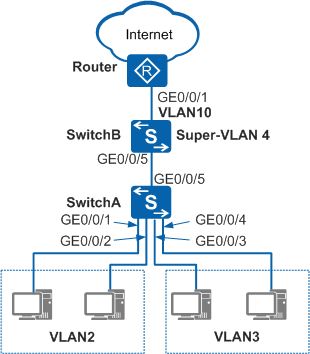
In Figure 1, an enterprise has many departments that reside on the same network segment. For security purposes, the enterprise adds different departments to different VLANs (VLAN 2 and VLAN 3). Each department requires access to the Internet and hosts from different departments need to communicate with each other.
Configuration Roadmap
Configure VLAN aggregation on SwitchB to add VLANs of different departments to a super-VLAN so that PCs in different departments can access the Internet using the super-VLAN. Deploy proxy ARP in the super-VLAN so that PCs from different departments can communicate. The configuration roadmap is as follows:
- Configure VLANs and interfaces on SwitchA and SwitchB, add hosts from different departments to different VLANs, and configure interfaces to transparently transmit packets from VLANs to SwitchB.
- Configure a super-VLAN, a VLANIF interface, and a static route on SwitchB to provide Internet access for hosts.
- Configure proxy ARP in the super-VLAN on SwitchB so that hosts from different departments can communicate at Layer 3.
Procedure
- Configure VLANs and interfaces on SwitchA and SwitchB, add hosts from different departments to different VLANs, and configure interfaces to transparently transmit packets from VLANs to SwitchB.
Configure SwitchA.
# Configure GE0/0/1 as an access interface. The configurations of GE0/0/2, GE0/0/3, and GE0/0/4 are similar to the configuration of GE0/0/1, and are not mentioned here.
<HUAWEI> system-view
[HUAWEI] sysname SwitchA
[SwitchA] interface gigabitethernet 0/0/1
[SwitchA-GigabitEthernet0/0/1] port link-type access
[SwitchA-GigabitEthernet0/0/1] quit
# Create VLAN 2 and add GE0/0/1 and GE0/0/2 to VLAN 2.
[SwitchA] vlan 2
[SwitchA-vlan2] port gigabitethernet 0/0/1 0/0/2
[SwitchA-vlan2] quit
# Create VLAN 3 and add GE0/0/3 and GE0/0/4 to VLAN 3.
[SwitchA] vlan 3
[SwitchA-vlan3] port gigabitethernet 0/0/3 0/0/4
[SwitchA-vlan3] quit
# Configure the interface of SwitchA connected to SwitchB to transparently transmit packets from VLAN 2 and VLAN 3 to SwitchB.
[SwitchA] interface gigabitethernet 0/0/5
[SwitchA-GigabitEthernet0/0/5] port link-type trunk
[SwitchA-GigabitEthernet0/0/5] port trunk allow-pass vlan 2 3
[SwitchA-GigabitEthernet0/0/5] quit
Configure SwitchB.
# Create VLAN 2, VLAN 3, VLAN 4, and VLAN 10 and configure the interface of SwitchB connected to SwitchA to transparently transmit packets from VLAN 2 and VLAN 3 to SwitchB.
<HUAWEI> system-view
[HUAWEI] sysname SwitchB
[SwitchB] vlan batch 2 3 4 10
[SwitchB] interface gigabitethernet 0/0/5
[SwitchB-GigabitEthernet0/0/5] port link-type trunk
[SwitchB-GigabitEthernet0/0/5] port trunk allow-pass vlan 2 3
[SwitchB-GigabitEthernet0/0/5] quit
- Configure a super-VLAN and a VLANIF interface corresponding to the super-VLAN.
# Configure super-VLAN 4 on SwitchB and add VLAN 2 and VLAN 3 to super-VLAN 4 as sub-VLANs.
[SwitchB] vlan 4
[SwitchB-vlan4] aggregate-vlan
[SwitchB-vlan4] access-vlan 2 to 3
[SwitchB-vlan4] quit
# Create and configure VLANIF 4 so that hosts in different departments can access the Internet using super-VLAN 4.
[SwitchB] interface vlanif 4
[SwitchB-Vlanif4] ip address 10.1.1.1 255.255.255.0
[SwitchB-Vlanif4] quit
- Configure a static route.
# Configure the uplink interface GE0/0/1 on SwitchB to transparently transmit packets from the VLAN to which SwitchB and the router belong.
[SwitchB] interface gigabitethernet 0/0/1
[SwitchB-GigabitEthernet0/0/1] port link-type trunk
[SwitchB-GigabitEthernet0/0/1] port trunk allow-pass vlan 10
[SwitchB-GigabitEthernet0/0/1] quit
# Create and configure VLANIF 10 and specify its IP address of VLANIF 10 as the IP address for connecting SwitchB and the router (egress gateway).
[SwitchB] interface vlanif 10
[SwitchB-Vlanif10] ip address 10.10.1.1 255.255.255.0
[SwitchB-Vlanif10] quit
# Configure a static route to the router on SwitchB so that hosts can access the Internet.
[SwitchB] ip route-static 0.0.0.0 0.0.0.0 10.10.1.2

Configure the router interface connected to SwitchB and assign to it the IP address of 10.10.1.2. For details, see the router configuration manual.
- Assign IP addresses to hosts.
Configure an IP address for each host. Ensure that the hosts reside on the same network segment as VLAN 4
After the preceding steps are complete, hosts in each department can access the Internet. However, the hosts in VLAN 2 and VLAN 3 cannot ping each other.
- Configure proxy ARP.
# Configure proxy ARP in super-VLAN 4 on SwitchB so that hosts in different departments can communicate at Layer 3.
[SwitchB] interface vlanif 4
[SwitchB-Vlanif4] arp-proxy inter-sub-vlan-proxy enable
[SwitchB-Vlanif4] quit
- Verify the configuration.
After the configuration is complete, hosts in VLAN 2 and VLAN 3 can ping each other and access the Internet.
Configuration Files
SwitchA configuration file
#
sysname SwitchA
#
vlan batch 2 to 3
#
interface GigabitEthernet0/0/1
 port link-type access
 port default vlan 2
#
interface GigabitEthernet0/0/2
 port link-type access
 port default vlan 2
#
interface GigabitEthernet0/0/3
 port link-type access
 port default vlan 3
#
interface GigabitEthernet0/0/4
 port link-type access
 port default vlan 3
#
interface GigabitEthernet0/0/5
 port link-type trunk
 port trunk allow-pass vlan 2 to 3
#
return
SwitchB configuration file
#
sysname SwitchB
#
vlan batch 2 to 4 10
#
vlan 4
 aggregate-vlan
 access-vlan 2 to 3
#
interface Vlanif4
 ip address 10.1.1.1 255.255.255.0
 arp-proxy inter-sub-vlan-proxy enable
#
interface Vlanif10
 ip address 10.10.1.1 255.255.255.0
#
interface GigabitEthernet0/0/1
 port link-type trunk
 port trunk allow-pass vlan 10
#
interface GigabitEthernet0/0/5
 port link-type trunk
 port trunk allow-pass vlan 2 to 3
#
ip route-static 0.0.0.0 0.0.0.0 10.10.1.2
#
return