Understanding TWAMP Light
TWAMP Communication Model
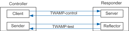
- Controller:
- Client: establishes, starts, and stops TWAMP sessions and collects statistics.
- Sender: sends performance measurement probes as requested by the Client.
- Responder:
- Server: responds to the Client's requests for establishing, starting, or stopping TWAMP sessions.
- Reflector: replies to the probes sent by the Sender as requested by the Server.
TWAMP-control packets are exchanged between the Client and Server to establish TWAMP sessions. TWAMP-test packets are exchanged between the Sender and Reflector for performance measurement.
TWAMP Light Communication Model
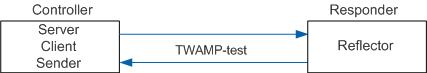
- Controller: sends and receives measurement session packets, collects performance statistics, and sends measurement results to the network management station (NMS).
- Responder: reflects the measurement session packets.
Measurement Implementation
TWAMP Light defines TWAMP-test packets in two directions as performance measurement probes. The Controller sends a test-request packet to the Responder, and then the Responder returns a test-response packet to the Controller, completing delay, jitter, and packet loss ratio measurement.
- Test-request: packet sent from Controller to Responder.
- Test-response: packet sent from Responder to Controller.
Delay
The probe sent by the Controller carries time stamp T0. The response probe sent by the Responder carries the receiving time stamp T1 and response time stamp T2. When receiving the response probe, the Controller records the receiving time stamp T3. Therefore, the data transmission delay within an interval is calculated based on the four time stamps.
Delay = T3 - T0 - (T2 - T1)
Jitter
A jitter is the absolute difference between the delays of two consecutive packets. For example, if the delay of a packet is S0, and the delay of the previous packet is S1, the jitter is as follows:
Jitter = | S0 - S1 |
Packet loss ratio
In a sampling interval, the test-request packet sent by Controller carries a sending sequence number. The Responder does not generate a sequence number, but copies the sequence number of the Controller as the response sequence number. The Controller records the number of sent test-request packets as N1, and the number of test-response packets received from the Responder as N2. Then the packet loss ratio within a sampling interval is as follows:
Packet loss ratio = (N1 - N2)/N1