Example for Configuring VBST
Networking Requirements
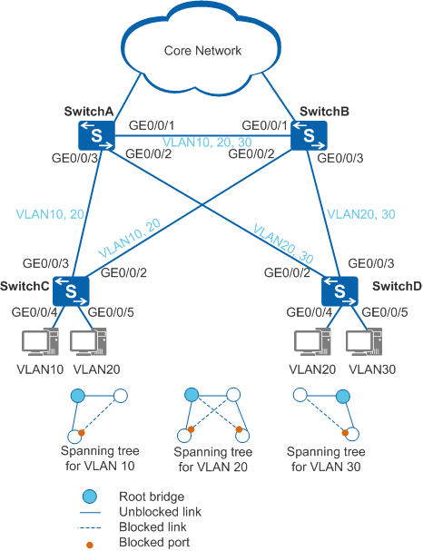
As shown in Figure 1, SwitchC and SwitchD (access switches) are dual-homed to SwitchA and SwitchB (aggregation switches) respectively. SwitchC transmits traffic from VLAN 10 and VLAN 20, and SwitchD transmits traffic from VLAN 20 and VLAN 30. A ring network is formed between the access layer and aggregation layer. The enterprise requires that service traffic in each VLAN be correctly forwarded and service traffic from different VLANs be load balanced to improve link use efficiency.
Configuration Roadmap
VBST can be used to eliminate loops between the access layer and aggregation layer and ensures that service traffic in each VLAN is correctly forwarded. In addition, traffic from different VLANs can be load balanced. The configuration roadmap is as follows:
- Configure Layer 2 forwarding on access and aggregation switches.
Configure basic VBST functions on SwitchA, SwitchB, SwitchC, and SwitchD. Perform the following operations so that a spanning tree shown in Figure 1 is formed through calculation:
- Configure the root bridge and secondary root bridge of VLAN 10 as SwitchA and SwitchB respectively, configure the root bridge and secondary root bridge of VLAN 20 as SwitchA and SwitchB respectively, and configure the root bridge and secondary root bridge of VLAN 30 as SwitchB and SwitchA respectively, to ensure root bridge reliability.
- Set a larger path cost for GE0/0/2 on SwitchC in VLAN 10 and VLAN 20 so that GE0/0/2 is blocked in spanning trees of VLAN 10 and VLAN 20 accordingly, set a larger path cost for GE0/0/2 on SwitchD in VLAN 20 and VLAN 30 so that GE0/0/2 is blocked in the spanning tree of VLAN 20 and VLAN 30 accordingly.
- Configure ports on SwitchC and SwitchD connected to terminals as edge ports to reduce VBST topology calculation and improve topology convergence.
Procedure
- Configure Layer 2 forwarding on switches on the ring network.
Create VLAN 10, VLAN 20, and VLAN 30 on SwitchA, SwitchB, SwitchC, and SwitchD.
# Create VLAN 10, VLAN 20, and VLAN 30 on SwitchA.
<HUAWEI> system-view
[HUAWEI] sysname SwitchA
[SwitchA] vlan batch 10 20 30
# Create VLAN 10, VLAN 20, and VLAN 30 on SwitchB.
<HUAWEI> system-view
[HUAWEI] sysname SwitchB
[SwitchB] vlan batch 10 20 30
# Create VLAN 10 and VLAN 20 on SwitchC.
<HUAWEI> system-view
[HUAWEI] sysname SwitchC
[SwitchC] vlan batch 10 20
# Create VLAN 20 and VLAN 30 on SwitchD.
<HUAWEI> system-view
[HUAWEI] sysname SwitchD
[SwitchD] vlan batch 20 30
Add ports connected to the ring to VLANs.
# Add GE0/0/1 on SwitchA to VLAN 10, VLAN 20, and VLAN 30.
[SwitchA] interface gigabitethernet 0/0/1
[SwitchA-GigabitEthernet0/0/1] port link-type trunk
[SwitchA-GigabitEthernet0/0/1] port trunk allow-pass vlan 10 20 30
[SwitchA-GigabitEthernet0/0/1] quit
# Add GE0/0/2 on SwitchA to VLAN 20 and VLAN 30.
[SwitchA] interface gigabitethernet 0/0/2
[SwitchA-GigabitEthernet0/0/2] port link-type trunk
[SwitchA-GigabitEthernet0/0/2] port trunk allow-pass vlan 20 30
[SwitchA-GigabitEthernet0/0/2] quit
# Add GE0/0/3 on SwitchA to VLAN 10 and VLAN 20.
[SwitchA] interface gigabitethernet 0/0/3
[SwitchA-GigabitEthernet0/0/3] port link-type trunk
[SwitchA-GigabitEthernet0/0/3] port trunk allow-pass vlan 10 20
[SwitchA-GigabitEthernet0/0/3] quit
# Add GE0/0/1 on SwitchB to VLAN 10, VLAN 20, and VLAN 30.
[SwitchB] interface gigabitethernet 0/0/1
[SwitchB-GigabitEthernet0/0/1] port link-type trunk
[SwitchB-GigabitEthernet0/0/1] port trunk allow-pass vlan 10 20 30
[SwitchB-GigabitEthernet0/0/1] quit
# Add GE0/0/2 on SwitchB to VLAN 10 and VLAN 20.
[SwitchB] interface gigabitethernet 0/0/2
[SwitchB-GigabitEthernet0/0/2] port link-type trunk
[SwitchB-GigabitEthernet0/0/2] port trunk allow-pass vlan 10 20
[SwitchB-GigabitEthernet0/0/2] quit
# Add GE0/0/3 on SwitchB to VLAN 20 and VLAN 30.
[SwitchB] interface gigabitethernet 0/0/3
[SwitchB-GigabitEthernet0/0/3] port link-type trunk
[SwitchB-GigabitEthernet0/0/3] port trunk allow-pass vlan 20 30
[SwitchB-GigabitEthernet0/0/3] quit
# Add GE0/0/2 on SwitchC to VLAN 10 and VLAN 20.
[SwitchC] interface gigabitethernet 0/0/2
[SwitchC-GigabitEthernet0/0/2] port link-type trunk
[SwitchC-GigabitEthernet0/0/2] port trunk allow-pass vlan 10 20
[SwitchC-GigabitEthernet0/0/2] quit
# Add GE0/0/3 on SwitchC to VLAN 10 and VLAN 20.
[SwitchC] interface gigabitethernet 0/0/3
[SwitchC-GigabitEthernet0/0/3] port link-type trunk
[SwitchC-GigabitEthernet0/0/3] port trunk allow-pass vlan 10 20
[SwitchC-GigabitEthernet0/0/3] quit
# Add GE0/0/4 on SwitchC to VLAN 10 and GE0/0/5 to VLAN 20.
[SwitchC] interface gigabitethernet 0/0/4
[SwitchC-GigabitEthernet0/0/4] port link-type access
[SwitchC-GigabitEthernet0/0/4] port default vlan 10
[SwitchC-GigabitEthernet0/0/4] quit
[SwitchC] interface gigabitethernet 0/0/5
[SwitchC-GigabitEthernet0/0/5] port link-type access
[SwitchC-GigabitEthernet0/0/5] port default vlan 20
[SwitchC-GigabitEthernet0/0/5] quit
# Add GE0/0/2 on SwitchD to VLAN 20 and VLAN 30.
[SwitchD] interface gigabitethernet 0/0/2
[SwitchD-GigabitEthernet0/0/2] port link-type trunk
[SwitchD-GigabitEthernet0/0/2] port trunk allow-pass vlan 20 30
[SwitchD-GigabitEthernet0/0/2] quit
# Add GE0/0/3 on SwitchD to VLAN 20 and VLAN 30.
[SwitchD] interface gigabitethernet 0/0/3
[SwitchD-GigabitEthernet0/0/3] port link-type trunk
[SwitchD-GigabitEthernet0/0/3] port trunk allow-pass vlan 20 30
[SwitchD-GigabitEthernet0/0/3] quit
# Add GE0/0/4 on SwitchD to VLAN 20 and GE0/0/5 to VLAN 30.
[SwitchD] interface gigabitethernet 0/0/4
[SwitchD-GigabitEthernet0/0/4] port link-type access
[SwitchD-GigabitEthernet0/0/4] port default vlan 20
[SwitchD-GigabitEthernet0/0/4] quit
[SwitchD] interface gigabitethernet 0/0/5
[SwitchD-GigabitEthernet0/0/5] port link-type access
[SwitchD-GigabitEthernet0/0/5] port default vlan 30
[SwitchD-GigabitEthernet0/0/5] quit
- Configure basic VBST functions.
Configure switches on the ring network to work in VBST mode.
# Configure SwitchA to work in VBST mode.
[SwitchA] stp mode vbst# Configure SwitchB to work in VBST mode.
[SwitchB] stp mode vbst# Configure SwitchC to work in VBST mode.
[SwitchC] stp mode vbst# Configure SwitchD to work in VBST mode.
[SwitchD] stp mode vbstConfigure the root bridge and secondary root bridge.
Configure the root bridge and secondary root bridge in VLAN 10.
# Configure SwitchA as the root bridge in VLAN 10.
[SwitchA] stp vlan 10 root primary# Configure SwitchB as the secondary root bridge in VLAN 10.
[SwitchB] stp vlan 10 root secondaryConfigure the root bridge and secondary root bridge in VLAN 20.
# Configure SwitchA as the root bridge in VLAN 20.
[SwitchA] stp vlan 20 root primary# Configure SwitchB as the secondary root bridge in VLAN 20.
[SwitchB] stp vlan 20 root secondaryConfigure the root bridge and secondary root bridge in VLAN 30.
# Configure SwitchB as the root bridge in VLAN 30.
[SwitchB] stp vlan 30 root primary# Configure SwitchA as the secondary root bridge in VLAN 30.
[SwitchA] stp vlan 30 root secondary
Configure the path cost for a port so that the port can be blocked.

The path cost range depends on the algorithm. IEEE 802.1t standard is used as an example. Set the path costs of the ports to be blocked to 2000000.
All switches on the same network must use the same path cost calculation method.
# Set the path cost of GE0/0/2 on SwitchC to 2000000 in VLAN 10 and VLAN 20.
[SwitchC] interface gigabitethernet 0/0/2
[SwitchC-GigabitEthernet0/0/2] stp vlan 10 cost 2000000
[SwitchC-GigabitEthernet0/0/2] stp vlan 20 cost 2000000
[SwitchC-GigabitEthernet0/0/2] quit
# Set the path cost of GE0/0/2 on SwitchD to 2000000 in VLAN 20 and VLAN 30.
[SwitchD] interface gigabitethernet 0/0/2
[SwitchD-GigabitEthernet0/0/2] stp vlan 20 cost 2000000
[SwitchD-GigabitEthernet0/0/2] stp vlan 30 cost 2000000
[SwitchD-GigabitEthernet0/0/2] quit
Enable VBST to eliminate loops.
Disable VBST in VLAN 1.
By default, all interfaces join VLAN 1 and VBST in VLAN 1 is enabled. In this example, to reduce spanning tree calculation, VBST is disabled in VLAN 1. To prevent loops in VLAN 1 after VBST is disabled, delete interfaces from VLAN 1.
# Disable VBST in VLAN 1 on SwitchA. The configurations on SwitchB, SwitchC, and SwitchD are similar to the configuration of SwitchA, and are not mentioned here.
[SwitchA] stp vlan 1 disable# Delete GE0/0/1 through GE0/0/3 on SwitchA from VLAN 1. The configurations on SwitchB, SwitchC, and SwitchD are similar to the configuration of SwitchA, and are not mentioned here. The difference is that GE0/0/4 and GE0/0/5 on SwitchC and SwitchD do not need to be removed from VLAN 1.
[SwitchA] interface gigabitethernet 0/0/1
[SwitchA-GigabitEthernet0/0/1] undo port trunk allow-pass vlan 1
[SwitchA-GigabitEthernet0/0/1] quit
[SwitchA] interface gigabitethernet 0/0/2
[SwitchA-GigabitEthernet0/0/2] undo port trunk allow-pass vlan 1
[SwitchA-GigabitEthernet0/0/2] quit
[SwitchA] interface gigabitethernet 0/0/3
[SwitchA-GigabitEthernet0/0/3] undo port trunk allow-pass vlan 1
[SwitchA-GigabitEthernet0/0/3] quit
Enable VBST globally.
# Enable global VBST on SwitchA.
[SwitchA] stp enable# Enable global VBST on SwitchB.
[SwitchB] stp enable# Enable global VBST on SwitchC.
[SwitchC] stp enable# Enable global VBST on SwitchD.
[SwitchD] stp enableEnable VBST globally.
By default, VBST is enabled globally.
Run the display stp global command to check the VBST status. If VBST is disabled, run the stp enable command in the system view to enable VBST globally.
Enable VBST in a VLAN.
By default, VBST is enabled in a VLAN.
Run the display stp vlan vlan-id command to check the VBST status. If the message "The protocol is disabled" is displayed, VBST is disabled in the VLAN. Run the stp vlan vlan-id enable command in the system view to enable VBST in the VLAN.
Enable VBST on ports.
By default, VBST is enabled on Layer 2 Ethernet ports.
Run the display stp interface interface-type interface-number command to check the VBST status on an interface. If the message "The protocol is disabled" is displayed, VBST is disabled on the interface. Run the stp enable command in the interface view to enable VBST on the interface.
- Configure ports connected to terminals as edge ports to improve topology convergence.
# Configure GE0/0/4 and GE0/0/5 on SwitchC connected to terminals as edge ports. The edge port configuration on SwitchD is similar to that of SwitchC, and is not mentioned here.
[SwitchC] interface gigabitethernet 0/0/4
[SwitchC-GigabitEthernet0/0/4] stp edged-port enable
[SwitchC-GigabitEthernet0/0/4] quit
[SwitchC] interface gigabitethernet 0/0/5
[SwitchC-GigabitEthernet0/0/5] stp edged-port enable
[SwitchC-GigabitEthernet0/0/5] quit
- Verify the configuration.
After the configuration is complete and the network topology becomes stable, perform the following operations to verify the configuration.
# Run the display stp bridge local command on SwitchA to view the STP working mode.
[SwitchA] display stp bridge local
VLAN-ID          Bridge ID Hello Max Forward Protocol
                            Time Age   Delay
----- -------------------- ----- --- ------- ---------------------------
   10    10.0200-0000-6703     2  20      15 VBST
   20    20.0200-0000-6703     2  20      15 VBST
   30  4126.0200-0000-6703     2  20      15 VBST
The preceding information shows that the VBST mode is used.
# Run the display stp brief command on SwitchA to view the port status.
[SwitchA] display stp brief
 VLAN-ID   Port                        Role  STP State     Protection
      10   GigabitEthernet0/0/1        DESI  FORWARDING    NONE
      10   GigabitEthernet0/0/3        DESI  FORWARDING    NONE
      20   GigabitEthernet0/0/1        DESI  FORWARDING    NONE
      20   GigabitEthernet0/0/2        DESI  FORWARDING    NONE
      20   GigabitEthernet0/0/3        DESI  FORWARDING    NONE
      30   GigabitEthernet0/0/1        ROOT  FORWARDING    NONE
      30   GigabitEthernet0/0/2        DESI  FORWARDING    NONE
The preceding information shows that SwitchA participates in spanning tree calculation in VLAN 10, VLAN 20, and VLAN 30. For example, SwitchA is the root bridge in VLAN 10 and VLAN 20, so GE0/0/1 and GE0/0/3 in VLAN 10 are selected as designated ports. GE0/0/1, GE0/0/2, and GE0/0/3 in VLAN 20 are selected as designated ports. SwitchA is the secondary root bridge in VLAN 30, so GE0/0/1 is selected as the root port and GE0/0/2 is selected as the designated port in VLAN 30.
# Run the display stp vlan 10 command on SwitchA to view detailed information about VLAN 10.
[SwitchA] display stp vlan 10
-------[VLAN 10 Global Info]-------
Bridge ID           :10   .0200-0000-6703
Config Times        :Hello 2s MaxAge 20s FwDly 15s
Active Times        :Hello 2s MaxAge 20s FwDly 15s
Root ID / RPC       :10   .0200-0000-6703 / 0 (This bridge is the root)
RootPortId          :0.0
Root Type           :Primary
 ----[Port4093(GigabitEthernet0/0/1)][FORWARDING]----
 Port Role          :Designated Port
 Port Priority      :128
 Port Cost(Dot1T)  :Config=Auto / Active=20000
 Desg. Bridge/Port  :10   .0200-0000-6703 / 128.4093
 Port Edged         :Config=Default / Active=Disabled
 Point-to-point     :Config=Auto / Active=true
 Transit Limit      :6 packets/hello
 Protection Type    :None
 ----[Port4092(GigabitEthernet0/0/3)][FORWARDING]----
 Port Role          :Designated Port
 Port Priority      :128
 Port Cost(Dot1T)  :Config=Auto / Active=199999
 Desg. Bridge/Port  :10   .0200-0000-6703 / 128.4092
 Port Edged         :Config=Default / Active=Disabled
 Point-to-point     :Config=Auto / Active=true
 Transit Limit      :6 packets/hello
 Protection Type    :None
The preceding information shows that SwitchA is selected as the root bridge in VLAN 10 and GE0/0/1 and GE0/0/3 are selected as designated ports in Forwarding state.
# Run the display stp brief command on SwitchB, SwitchC, and SwitchD to view the port status.
[SwitchB] display stp brief
 VLAN-ID   Port                        Role  STP State     Protection
      10   GigabitEthernet0/0/1        ROOT  FORWARDING    NONE
      10   GigabitEthernet0/0/2        DESI  FORWARDING    NONE
      20   GigabitEthernet0/0/1        ROOT  FORWARDING    NONE
      20   GigabitEthernet0/0/2        DESI  FORWARDING    NONE
      20   GigabitEthernet0/0/3        DESI  FORWARDING    NONE
      30   GigabitEthernet0/0/1        DESI  FORWARDING    NONE
      30   GigabitEthernet0/0/3        DESI  FORWARDING    NONE
[SwitchC] display stp brief
 VLAN-ID   Port                        Role  STP State     Protection
      10   GigabitEthernet0/0/2        ALTE  DISCARDING    NONE
      10   GigabitEthernet0/0/3        ROOT  FORWARDING    NONE
      10   GigabitEthernet0/0/4        DESI  FORWARDING    NONE
      20   GigabitEthernet0/0/2        ALTE  DISCARDING    NONE
      20   GigabitEthernet0/0/3        ROOT  FORWARDING    NONE
      20   GigabitEthernet0/0/5        DESI  FORWARDING    NONE
[SwitchD] display stp brief
 VLAN-ID   Port                        Role  STP State     Protection
      20   GigabitEthernet0/0/2        ALTE  DISCARDING    NONE
      20   GigabitEthernet0/0/3        ROOT  FORWARDING    NONE
      20   GigabitEthernet0/0/4        DESI  FORWARDING    NONE
      30   GigabitEthernet0/0/2        ALTE  DISCARDING    NONE
      30   GigabitEthernet0/0/3        ROOT  FORWARDING    NONE
      30   GigabitEthernet0/0/5        DESI  FORWARDING    NONE
The preceding information shows that SwitchB participates in spanning tree calculation in VLAN 10, VLAN 20, and VLAN 30, SwitchC participates in spanning tree calculation in VLAN 10 and VLAN 20, and SwitchD participates in spanning tree calculation in VLAN 20 and VLAN 30. After the calculation is complete, ports are selected as different roles to eliminate loops.
Different spanning trees are formed in VLAN 10, VLAN 20, and VLAN 30, and traffic in VLAN 10, VLAN 20, and VLAN 30 is forwarded along different spanning trees to implement load balancing.
Configuration Files
SwitchA configuration file
#
sysname SwitchA
#
vlan batch 10 20 30
#
stp mode vbst
#
stp vlan 1 disable
stp vlan 30 root secondary
stp vlan 10 20 root primary
#
interface GigabitEthernet0/0/1
 port link-type trunk
 undo port trunk allow-pass vlan 1
 port trunk allow-pass vlan 10 20 30
#
interface GigabitEthernet0/0/2
 port link-type trunk
 undo port trunk allow-pass vlan 1
 port trunk allow-pass vlan 20 30
#
interface GigabitEthernet0/0/3
 port link-type trunk
 undo port trunk allow-pass vlan 1
 port trunk allow-pass vlan 10 20
#
return
SwitchB configuration file
#
sysname SwitchB
#
vlan batch 10 20 30
#
stp mode vbst
#
stp vlan 1 disable
stp vlan 10 20 root secondary
stp vlan 30 root primary
#
interface GigabitEthernet0/0/1
 port link-type trunk
 undo port trunk allow-pass vlan 1
 port trunk allow-pass vlan 10 20 30
#
interface GigabitEthernet0/0/2
 port link-type trunk
 undo port trunk allow-pass vlan 1
 port trunk allow-pass vlan 10 20
#
interface GigabitEthernet0/0/3
 port link-type trunk
 undo port trunk allow-pass vlan 1
 port trunk allow-pass vlan 20 30
#
return
SwitchC configuration file
#
sysname SwitchC
#
vlan batch 10 20
#
stp mode vbst
#
stp vlan 1 disable
#
interface GigabitEthernet0/0/2
 port link-type trunk
 undo port trunk allow-pass vlan 1
 port trunk allow-pass vlan 10 20
 stp vlan 10 20 cost 2000000
#
interface GigabitEthernet0/0/3
 port link-type trunk
 undo port trunk allow-pass vlan 1
 port trunk allow-pass vlan 10 20
#
interface GigabitEthernet0/0/4
 port link-type access
 port default vlan 10
 stp edged-port enable
#
interface GigabitEthernet0/0/5
 port link-type access
 port default vlan 20
 stp edged-port enable
#
return
SwitchD configuration file
#
sysname SwitchD
#
vlan batch 20 30
#
stp mode vbst
#
stp vlan 1 disable
#
interface GigabitEthernet0/0/2
 port link-type trunk
 undo port trunk allow-pass vlan 1
 port trunk allow-pass vlan 20 30
 stp vlan 20 30 cost 2000000
#
interface GigabitEthernet0/0/3
 port link-type trunk
 undo port trunk allow-pass vlan 1
 port trunk allow-pass vlan 20 30
#
interface GigabitEthernet0/0/4
 port link-type access
 port default vlan 20
 stp edged-port enable
#
interface GigabitEthernet0/0/5
 port link-type access
 port default vlan 30
 stp edged-port enable
#
return