Example for Configuring VLAN ID-based N:1 VLAN Mapping
Networking Requirements

This example configures the N:1 mode for 1 to 1 VLAN mapping.
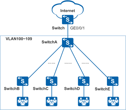
In Figure 1, a large number of switches need to be deployed at the corridor so that the same service used by different users can be sent on different VLANs. To save VLAN resources, configure the VLAN aggregation function (N:1) on the switches so that same services are sent on the same VLAN.
Configuration Roadmap
The configuration roadmap is as follows:
Create the original VLAN and the translated VLAN on the Switch and add GE0/0/1 to the VLANs in tagged mode.
Configure VLAN mapping on GE0/0/1 on the Switch.
Procedure
- Configure the Switch.
# Create a VLAN.
<HUAWEI> system-view
[HUAWEI] sysname Switch
[Switch] vlan batch 10 100 to 109
# Add GE0/0/1 to the VLAN.
[Switch] interface gigabitethernet 0/0/1
[Switch-GigabitEthernet0/0/1] port link-type hybrid
[Switch-GigabitEthernet0/0/1] port hybrid tagged vlan 10 100 to 109
# Configure VLAN mapping on GE0/0/1.
[Switch-GigabitEthernet0/0/1] qinq vlan-translation enable
[Switch-GigabitEthernet0/0/1] port vlan-mapping vlan 100 to 109 map-vlan 10
- Verify the configurations.
Verify that users in VLAN 100 to VLAN 109 can connect to the Internet through the Switch.