Example for Configuring Inter-AS Kompella VPLS in OptionA Mode
Networking Requirements
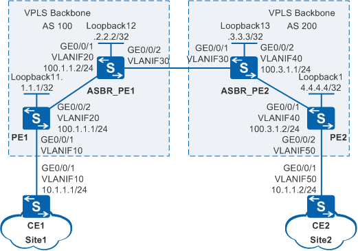
As shown in Figure 1, on an enterprise network, Site1 connects to PE1 through CE1 and then connects to the VPLS domain of AS 100. Site2 connects to PE2 through CE2 and then connects to the VPLS domain of AS 200. The network environments of the branch sites are unstable. AS 100 and AS 200 communicate with each other through ASBR_PE1 and ASBR_PE2. IS-IS is used as the IGP on the MPLS backbone network in an AS. Users at Site1 and Site2 need to communicate at Layer 2 and user information needs to be reserved when Layer 2 packets are transmitted over the backbone network.
Configuration Roadmap
The configuration roadmap is as follows:
Configure transparent transmission of Layer 2 packets over the backbone network using VPLS to enable users at Site1 and Site2 to communicate at Layer 2 and reserve user information when Layer 2 packets are transmitted over the backbone network.
Use Kompella VPLS to implement Layer 2 communication between CEs when the network environments of the branch sites are unstable.
Configure the IGP routing protocol on the backbone network to implement communication between devices within an AS on the public network.
Configure basic MPLS functions and LDP on PEs on the backbone network to support VPLS.
Establish tunnels for transmitting data between PEs within an AS to prevent data from being known by the public network.
Enable MPLS L2VPN on PEs to implement VPLS.
Enable BGP peers to exchange VPLS information between PEs within an AS, create a VSI on each PE switch, specify BGP as the signaling protocol, specify the RD, VPN target, and site of the VSI, and bind AC interfaces to VSIs to implement Kompella VPLS.
To implement VPLS inter-AS OptionA, configure the peer ASBR as the CE on the ASBR PE, and bind VSIs to peer interfaces.
Procedure
- Configure VLANs that interfaces belong to.
Configure the VLAN that each interface belongs to and assign IP addresses to interfaces on Switch.
# Configure CE1. The configuration on PE1, PE2, ASBR_PE1, ASBR_PE2, and CE2 is similar to the CE1, and is not mentioned here.
<HUAWEI> system-view
[HUAWEI] sysname CE1
[CE1] vlan 10
[CE1-vlan10] quit
[CE1] interface vlanif 10
[CE1-Vlanif10] ip address 10.1.1.1 255.255.255.0
[CE1-Vlanif10] quit
[CE1] interface gigabitethernet 0/0/1
[CE1-GigabitEthernet0/0/1] port link-type trunk
[CE1-GigabitEthernet0/0/1] port trunk allow-pass vlan 10
[CE1-GigabitEthernet0/0/1] quit

Do not add AC-side physical interfaces and PW-side physical interfaces of a PE to the same VLAN; otherwise, a loop may occur.
- Configure the IGP on the MPLS backbone network.
Configure the IGP on the MPLS backbone network to achieve connectivity between the PEs and ASBR PEs. Note that IS-IS must be enabled on Loopback1.
Configure IS-IS between on PE1 and ASBR_PE1, and between PE2, and ASBR_PE2.
# Configure PE1. The configuration on ASBR_PE1, ASBR_PE2, and PE2 is similar to the PE1, and is not mentioned here.
[PE1] isis 1
[PE1-isis-1] network-entity 10.0000.0000.0001.00
[PE1-isis-1] quit
[PE1] interface loopback 1
[PE1-LoopBack1] ip address 1.1.1.1 255.255.255.255
[PE1-LoopBack1] isis enable 1
[PE1-LoopBack1] quit
[PE1] interface vlanif 20
[PE1-Vlanif20] isis enable 1
[PE1-Vlanif20] quit
After the configuration is complete, the IS-IS peer relationship is established between the ASBR PE and PE in the same AS. Run the display isis peer command, and you can see that the status of the IS-IS peer relationship is Up.
The information displayed on PE1 is used as an example.
[PE1] display isis peer

                          Peer information for ISIS(1)

  System Id     Interface          Circuit Id       State HoldTime Type     PRI
-------------------------------------------------------------------------------
0000.0000.0002  Vlanif20           0000.0000.0002.01 Up   8s       L1(L1L2) 64
0000.0000.0002  Vlanif20           0000.0000.0002.01 Up   8s       L2(L1L2) 64

Total Peer(s): 2
ASBR-PEs and PEs in the same AS can ping Loopback1 of each other successfully. ASBR_PE1 is used as an example.
[ASBR_PE1] ping 1.1.1.1 PING 1.1.1.1: 56 data bytes, press CTRL_C to break Reply from 1.1.1.1: bytes=56 Sequence=1 ttl=255 time=47 ms Reply from 1.1.1.1: bytes=56 Sequence=2 ttl=255 time=31 ms Reply from 1.1.1.1: bytes=56 Sequence=3 ttl=255 time=31 ms Reply from 1.1.1.1: bytes=56 Sequence=4 ttl=255 time=31 ms Reply from 1.1.1.1: bytes=56 Sequence=5 ttl=255 time=31 ms --- 1.1.1.1 ping statistics --- 5 packet(s) transmitted 5 packet(s) received 0.00% packet loss round-trip min/avg/max = 31/34/47 ms - Configure basic MPLS functions and LDP.
Enable basic MPLS functions on the MPLS backbone network. Establish a dynamic LDP LSP between the PE and ASBR PE in the same AS.
Configure basic MPLS functions and LDP on PE1, ASBR_PE1, PE2, and ASBR_PE2.
# Configure PE1. The configuration on ASBR_PE1, ASBR_PE2, and PE2 is similar to the PE1, and is not mentioned here.
[PE1] mpls lsr-id 1.1.1.1
[PE1] mpls
[PE1-mpls] quit
[PE1] mpls ldp
[PE1-mpls-ldp] quit
[PE1] interface vlanif 20
[PE1-Vlanif20] mpls
[PE1-Vlanif20] mpls ldp
[PE1-Vlanif20] quit
After the configuration is complete, run the display mpls lsp command on PEs, and you can see that the LSP is established between the PE and the ASBR-PE in the same AS.
The information displayed on PE1 is used as an example.
[PE1] display mpls lsp Flag after Out IF: (I) - LSP Is Only Iterated by RLFA ------------------------------------------------------------------------------- LSP Information: LDP LSP ------------------------------------------------------------------------------- FEC In/Out Label In/Out IF Vrf Name 1.1.1.1/32 3/NULL -/- 2.2.2.2/32 NULL/3 -/Vlanif20 2.2.2.2/32 1025/3 -/Vlanif20 - Configure MP IBGP connections within an AS.
Establish the MP IBGP connection and enable BGP VPLS.
# Configure PE1.
[PE1] bgp 100
[PE1-bgp] peer 2.2.2.2 as-number 100
[PE1-bgp] peer 2.2.2.2 connect-interface loopback 1
[PE1-bgp] vpls-family
[PE1-bgp-af-vpls] peer 2.2.2.2 enable
[PE1-bgp-af-vpls] quit
[PE1-bgp] quit
# Configure ASBR_PE1.
[ASBR_PE1] bgp 100
[ASBR_PE1-bgp] peer 1.1.1.1 as-number 100
[ASBR_PE1-bgp] peer 1.1.1.1 connect-interface loopback 1
[ASBR_PE1-bgp] vpls-family
[ASBR_PE1-bgp-af-vpls] peer 1.1.1.1 enable
[ASBR_PE1-bgp-af-vpls] quit
[ASBR_PE1-bgp] quit
# Configure PE2.
[PE2] bgp 200
[PE2-bgp] peer 3.3.3.3 as-number 200
[PE2-bgp] peer 3.3.3.3 connect-interface loopBack1
[PE2-bgp] vpls-family
[PE2-bgp-af-vpls] peer 3.3.3.3 enable
[PE2-bgp-af-vpls] quit
[PE2-bgp] quit
# Configure ASBR_PE2.
[ASBR_PE2] bgp 200
[ASBR_PE2-bgp] peer 4.4.4.4 as-number 200
[ASBR_PE2-bgp] peer 4.4.4.4 connect-interface loopback 1
[ASBR_PE2-bgp] vpls-family
[ASBR_PE2-bgp-af-vpls] peer 4.4.4.4 enable
[ASBR_PE2-bgp-af-vpls] quit
[ASBR_PE2-bgp] quit
Run the display bgp vpls peer command on the PE or ASBR PE, and you can see that MP-IBGP peers between the PEs are in Established state.
The information displayed on PE1 is used as an example.
[PE1] display bgp vpls peer BGP local router ID : 1.1.1.1 Local AS number : 100 Total number of peers : 1 Peers in established state : 1 Peer V AS MsgRcvd MsgSent OutQ Up/Down State PrefRcv 2.2.2.2 4 100 5 8 0 00:02:13 Established 0 - Enable MPLS L2VPN on PEs and ASBR-PEs.
# Configure PE1.
[PE1] mpls l2vpn
[PE1-l2vpn] quit
# Configure ASBR_PE1.
[ASBR_PE1] mpls l2vpn
[ASBR_PE1-l2vpn] quit
# Configure ASBR_PE2.
[ASBR_PE2] mpls l2vpn
[ASBR_PE2-l2vpn] quit
# Configure PE2.
[PE2] mpls l2vpn
[PE2-l2vpn] quit
- Configure VSIs on PEs and ASBRs, and bind VSIs to AC interfaces.
# Configure PE1.
[PE1] vsi v1 auto
[PE1-vsi-v1] pwsignal bgp
[PE1-vsi-v1-bgp] route-distinguisher 100:1
[PE1-vsi-v1-bgp] vpn-target 1:1 import-extcommunity
[PE1-vsi-v1-bgp] vpn-target 1:1 export-extcommunity
[PE1-vsi-v1-bgp] site 1 range 5 default-offset 0
[PE1-vsi-v1-bgp] quit
[PE1-vsi-v1] quit
[PE1] interface vlanif 10
[PE1-Vlanif10] l2 binding vsi v1
[PE1-Vlanif10] quit
# Configure ASBR_PE1.
[ASBR_PE1] vsi v1 auto
[ASBR_PE1-vsi-v1] pwsignal bgp
[ASBR_PE1-vsi-v1-bgp] route-distinguisher 100:2
[ASBR_PE1-vsi-v1-bgp] vpn-target 1:1 import-extcommunity
[ASBR_PE1-vsi-v1-bgp] vpn-target 1:1 export-extcommunity
[ASBR_PE1-vsi-v1-bgp] site 2 range 5 default-offset 0
[ASBR_PE1-vsi-v1-bgp] quit
[ASBR_PE1-vsi-v1] quit
[ASBR_PE1] interface vlanif 30
[ASBR_PE1-Vlanif30] l2 binding vsi v1
[ASBR_PE1-Vlanif30] quit
# Configure ASBR_PE2.
[ASBR_PE2] vsi v1 auto
[ASBR_PE2-vsi-v1] pwsignal bgp
[ASBR_PE2-vsi-v1-bgp] route-distinguisher 200:1
[ASBR_PE2-vsi-v1-bgp] vpn-target 1:1 import-extcommunity
[ASBR_PE2-vsi-v1-bgp] vpn-target 1:1 export-extcommunity
[ASBR_PE2-vsi-v1-bgp] site 1 range 5 default-offset 0
[ASBR_PE2-vsi-v1-bgp] quit
[ASBR_PE2-vsi-v1] quit
[ASBR_PE2] interface vlanif 30
[ASBR_PE2-Vlanif30] l2 binding vsi v1
[ASBR_PE2-Vlanif30] quit
# Configure PE2.
[PE2] vsi v1 auto
[PE2-vsi-v1] pwsignal bgp
[PE2-vsi-v1-bgp] route-distinguisher 200:2
[PE2-vsi-v1-bgp] vpn-target 1:1 import-extcommunity
[PE2-vsi-v1-bgp] vpn-target 1:1 export-extcommunity
[PE2-vsi-v1-bgp] site 2 range 5 default-offset 0
[PE2-vsi-v1-bgp] quit
[PE2-vsi-v1] quit
[PE2] interface vlanif 50
[PE2-Vlanif50] l2 binding vsi v1
[PE2-Vlanif50] quit
- Verify the configuration.
Run the display vpls connection bgp command on a PE, and you can see that the VSI status is Up.
The information displayed on PE1 is used as an example.
[PE1] display vpls connection bgp verbose
VSI Name: v1                               Signaling: bgp
  **Remote Site ID     : 2
    VC State           : up
    RD                 : 100:2
    Encapsulation      : vlan
    MTU                : 1500
    Peer Ip Address    : 2.2.2.2
    PW Type            : label
    Local VC Label     : 35842
    Remote VC Label    : 31745
    Tunnel Policy      : --
    Tunnel ID          : 0x20020
    Remote Label Block : 31744/5/0
    Export vpn target  : 1:1
CE1 and CE2 can ping each other successfully.
[CE1] ping 10.1.1.2
  PING 10.1.1.2: 56  data bytes, press CTRL_C to break
    Reply from 10.1.1.2: bytes=56 Sequence=1 ttl=255 time=90 ms
    Reply from 10.1.1.2: bytes=56 Sequence=2 ttl=255 time=77 ms
    Reply from 10.1.1.2: bytes=56 Sequence=3 ttl=255 time=34 ms
    Reply from 10.1.1.2: bytes=56 Sequence=4 ttl=255 time=46 ms
    Reply from 10.1.1.2: bytes=56 Sequence=5 ttl=255 time=94 ms

  --- 10.1.1.2 ping statistics ---
    5 packet(s) transmitted
    5 packet(s) received
    0.00% packet loss
    round-trip min/avg/max = 34/68/94 ms
Run the display bgp vpls all command on a PE or an ASBR-PE, and you can see information about the VPLS label block of BGP.
The information displayed on ASBR_PE1 is used as an example.
[ASBR_PE1] display bgp vpls all
BGP Local Router ID : 2.2.2.2, Local AS Number : 100
Status codes : * - active, > - best
BGP.VPLS : 2 Label Blocks

--------------------------------------------------------------------------------
Route Distinguisher: 100:1
   SiteID Offset NextHop         Range LabBase TunnelID   FromPeer        MHPref
--------------------------------------------------------------------------------
*> 1      0      1.1.1.1         5     31744   0x0        1.1.1.1         0

--------------------------------------------------------------------------------
Route Distinguisher: 100:2
   SiteID Offset NextHop         Range LabBase TunnelID   FromPeer        MHPref
--------------------------------------------------------------------------------
>  2      0      0.0.0.0         5     31744   0x0        0.0.0.0         0
Configuration Files
CE1 configuration file
#
sysname CE1
#
vlan batch 10
#
interface Vlanif10
 ip address 10.1.1.1 255.255.255.0
#
interface GigabitEthernet0/0/1
 port link-type trunk
 port trunk allow-pass vlan 10
#
return
PE1 configuration file
#
sysname PE1
#
vlan batch 10 20
#
mpls lsr-id 1.1.1.1
mpls
#
mpls l2vpn
#
vsi v1 auto
 pwsignal bgp
  route-distinguisher 100:1
  vpn-target 1:1 import-extcommunity
  vpn-target 1:1 export-extcommunity
  site 1 range 5 default-offset 0
#
mpls ldp
#
isis 1
 network-entity 10.0000.0000.0001.00
#
interface Vlanif10
 l2 binding vsi v1
#
interface Vlanif20
 ip address 100.1.1.1 255.255.255.0
 isis enable 1
 mpls
 mpls ldp
#
interface GigabitEthernet0/0/1
 port link-type trunk
 port trunk allow-pass vlan 10
#
interface GigabitEthernet0/0/2
 port link-type trunk
 port trunk allow-pass vlan 20
#
interface LoopBack1
 ip address 1.1.1.1 255.255.255.255
 isis enable 1
#
bgp 100
 peer 2.2.2.2 as-number 100
 peer 2.2.2.2 connect-interface LoopBack1
 #
 ipv4-family unicast
  undo synchronization
  peer 2.2.2.2 enable
 #
 vpls-family
  policy vpn-target
  peer 2.2.2.2 enable
#
return
ASBR_PE1 configuration file
#
sysname ASBR_PE1
#
vlan batch 20 30
#
mpls lsr-id 2.2.2.2
mpls
#
mpls l2vpn
#
vsi v1 auto
 pwsignal bgp
  route-distinguisher 100:2
  vpn-target 1:1 import-extcommunity
  vpn-target 1:1 export-extcommunity
  site 2 range 5 default-offset 0
#
mpls ldp
#
isis 1
 network-entity 10.0000.0000.0002.00
#
interface Vlanif20
 ip address 100.1.1.2 255.255.255.0
 isis enable 1
 mpls
 mpls ldp
#
interface Vlanif30
 l2 binding vsi v1
#
interface GigabitEthernet0/0/1
 port link-type trunk
 port trunk allow-pass vlan 20
#
interface GigabitEthernet0/0/2
 port link-type trunk
 port trunk allow-pass vlan 30
#
interface LoopBack1
 ip address 2.2.2.2 255.255.255.255
 isis enable 1
#
bgp 100
 peer 1.1.1.1 as-number 100
 peer 1.1.1.1 connect-interface LoopBack1
 #
 ipv4-family unicast
  undo synchronization
  peer 1.1.1.1 enable
 #
 vpls-family
  policy vpn-target
  peer 1.1.1.1 enable
#
return
ASBR_PE2 configuration file
#
sysname ASBR_PE2
#
vlan batch 30 40
#
mpls lsr-id 3.3.3.3
mpls
#
mpls l2vpn
#
vsi v1 auto
 pwsignal bgp
  route-distinguisher 200:1
  vpn-target 1:1 import-extcommunity
  vpn-target 1:1 export-extcommunity
  site 1 range 5 default-offset 0
#
mpls ldp
#
isis 1
 network-entity 10.0000.0000.0003.00
#
interface Vlanif30
 l2 binding vsi v1
#
interface Vlanif40
 ip address 100.3.1.1 255.255.255.0
 isis enable 1
 mpls
 mpls ldp
#
interface GigabitEthernet0/0/1
 port link-type trunk
 port trunk allow-pass vlan 30
#
interface GigabitEthernet0/0/2
 port link-type trunk
 port trunk allow-pass vlan 40
#
interface LoopBack1
 ip address 3.3.3.3 255.255.255.255
 isis enable 1
#
bgp 200
 peer 4.4.4.4 as-number 200
 peer 4.4.4.4 connect-interface LoopBack1
 #
 ipv4-family unicast
  undo synchronization
  peer 4.4.4.4 enable
 #
 vpls-family
  policy vpn-target
  peer 4.4.4.4 enable
#
return
PE2 configuration file
#
sysname PE2
#
vlan batch 40 50
#
mpls lsr-id 4.4.4.4
mpls
#
mpls l2vpn
#
vsi v1 auto
 pwsignal bgp
  route-distinguisher 200:2
  vpn-target 1:1 import-extcommunity
  vpn-target 1:1 export-extcommunity
  site 2 range 5 default-offset 0
#
mpls ldp
#
isis 1
 network-entity 10.0000.0000.0004.00
#
interface Vlanif40
 ip address 100.3.1.2 255.255.255.0
 isis enable 1
 mpls
 mpls ldp
#
interface Vlanif50
 l2 binding vsi v1
#
interface GigabitEthernet0/0/1
 port link-type trunk
 port trunk allow-pass vlan 40
#
interface GigabitEthernet0/0/2
 port link-type trunk
 port trunk allow-pass vlan 50
#
interface LoopBack1
 ip address 4.4.4.4 255.255.255.255
 isis enable 1
#
bgp 200
 peer 3.3.3.3 as-number 200
 peer 3.3.3.3 connect-interface LoopBack1
 #
 ipv4-family unicast
  undo synchronization
  peer 3.3.3.3 enable
 #
 vpls-family
  policy vpn-target
  peer 3.3.3.3 enable
#
return
CE2 configuration file
#
sysname CE2
#
vlan batch 50
#
interface Vlanif50
 ip address 10.1.1.2 255.255.255.0
#
interface GigabitEthernet0/0/1
 port link-type trunk
 port trunk allow-pass vlan 50
#
return