Example for Configuring a VRRP6 Group in Redundancy Mode
Networking Requirements
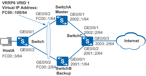
The host uses SwitchA as the default gateway to connect to the Internet. When SwitchA becomes faulty, SwitchB functions as the gateway. This implements gateway backup.
After SwitchA recovers, it preempts to be the master to transmit data after a preemption delay of 20s.

In this scenario, to avoid loops, ensure that all connected interfaces have STP disabled and connected interfaces are removed from VLAN 1. If STP is enabled and VLANIF interfaces of switches are used to construct a Layer 3 ring network, an interface on the network will be blocked. As a result, Layer 3 services on the network cannot run normally.
Device |
Interface |
VLANIF Interface |
IP Address |
|---|---|---|---|
SwitchA |
GE0/0/1 |
VLANIF 300 |
2002::1/64 |
GE0/0/2 |
VLANIF 100 |
FC00::1/64 |
|
SwitchB |
GE0/0/1 |
VLANIF 200 |
2001::1/64 |
GE0/0/2 |
VLANIF 100 |
FC00::2/64 |
|
SwitchC |
GE0/0/1 |
VLANIF 300 |
2002::2/64 |
GE0/0/2 |
VLANIF 200 |
2001::2/64 |
|
GE0/0/3 |
VLANIF 400 |
2003::2/64 |
Configuration Roadmap
The configuration roadmap is as follows:
- Assign an IP address to each interface and configure a routing protocol to ensure network connectivity.
- Configure a VRRP6 group on SwitchA and SwitchB, set the preemption delay to 20s and a higher priority for SwitchA so that SwitchA functions as the master to forward traffic, and set a lower priority for SwitchB so that SwitchB functions as the backup.
Procedure
- Configure devices to ensure network connectivity.
# Configure VLANs to which each interface belongs. SwitchA is used as an example. The configurations of SwitchB and SwitchC are similar to the configuration of SwitchA. For details, see the configuration files.
<HUAWEI> system-view
[HUAWEI] sysname SwitchA
[SwitchA] vlan batch 100 300
[SwitchA] interface gigabitethernet 0/0/1
[SwitchA-GigabitEthernet0/0/1] port link-type hybrid
[SwitchA-GigabitEthernet0/0/1] port hybrid pvid vlan 300
[SwitchA-GigabitEthernet0/0/1] port hybrid untagged vlan 300
[SwitchA-GigabitEthernet0/0/1] quit
[SwitchA] interface gigabitethernet 0/0/2
[SwitchA-GigabitEthernet0/0/2] port link-type hybrid
[SwitchA-GigabitEthernet0/0/2] port hybrid pvid vlan 100
[SwitchA-GigabitEthernet0/0/2] port hybrid untagged vlan 100
[SwitchA-GigabitEthernet0/0/2] quit
# Assign an IP address to each interface. SwitchA is used as an example. The configurations of SwitchB and SwitchC are similar to the configuration of SwitchA. For details, see the configuration files.
[SwitchA] ipv6
[SwitchA] interface vlanif 100
[SwitchA-Vlanif100] ipv6 enable
[SwitchA-Vlanif100] ipv6 address FC00::1 64
[SwitchA-Vlanif100] quit
[SwitchA] interface vlanif 300
[SwitchA-Vlanif300] ipv6 enable
[SwitchA-Vlanif300] ipv6 address 2002::1 64
[SwitchA-Vlanif300] quit
# Configure Layer 2 transmission on the switch.
<HUAWEI> system-view
[HUAWEI] sysname Switch
[Switch] vlan 100
[Switch-vlan100] quit
[Switch] interface gigabitethernet 0/0/1
[Switch-GigabitEthernet0/0/1] port link-type hybrid
[Switch-GigabitEthernet0/0/1] port hybrid pvid vlan 100
[Switch-GigabitEthernet0/0/1] port hybrid untagged vlan 100
[Switch-GigabitEthernet0/0/1] quit
[Switch] interface gigabitethernet 0/0/2
[Switch-GigabitEthernet0/0/2] port link-type hybrid
[Switch-GigabitEthernet0/0/2] port hybrid pvid vlan 100
[Switch-GigabitEthernet0/0/2] port hybrid untagged vlan 100
[Switch-GigabitEthernet0/0/2] quit
# Configure OSPFv3 between SwitchA, SwitchB, and SwitchC. SwitchA is used as an example. The configurations of SwitchB and SwitchC are similar to the configuration of SwitchA. For details, see the configuration files.
[SwitchA] ospfv3
[SwitchA-ospfv3-1] router-id 1.1.1.1
[SwitchA-ospfv3-1] quit
[SwitchA] interface vlanif 100
[SwitchA-Vlanif100] ospfv3 1 area 0
[SwitchA-Vlanif100] quit
[SwitchA] interface vlanif 300
[SwitchA-Vlanif300] ospfv3 1 area 0
[SwitchA-Vlanif300] quit
- Configure VRRP6 groups.
# Configure VRRP6 group 1 on SwitchA, and set the priority of SwitchA to 120 and the preemption delay to 20s.
[SwitchA] interface vlanif 100
[SwitchA-Vlanif100] vrrp6 vrid 1 virtual-ip FE80::1 link-local
[SwitchA-Vlanif100] vrrp6 vrid 1 virtual-ip FC00::100
[SwitchA-Vlanif100] vrrp6 vrid 1 priority 120
[SwitchA-Vlanif100] vrrp6 vrid 1 preempt-mode timer delay 20
[SwitchA-Vlanif100] quit
# Configure VRRP6 group 1 on SwitchB, and set the default priority of 100 for SwitchB.
[SwitchB] interface vlanif 100
[SwitchB-Vlanif100] vrrp6 vrid 1 virtual-ip FE80::1 link-local
[SwitchB-Vlanif100] vrrp6 vrid 1 virtual-ip FC00::100
[SwitchB-Vlanif100] quit
- Verify the configuration.
# Run the display vrrp6 command on SwitchA and SwitchB. You can see that SwitchA is in Master state and SwitchB is in Backup state.
[SwitchA] display vrrp6 Vlanif100 | Virtual Router 1 State : Master Virtual IP : FE80::1 FC00::100 Master IP : FE80::218:82FF:FED3:2AF3 PriorityRun : 120 PriorityConfig : 120 MasterPriority : 120 Preempt : YES Delay Time : 20 s TimerRun : 100 cs TimerConfig : 100 cs Virtual MAC : 0000-5e00-0201 Check hop limit : YES Config type : normal-vrrp Backup-forward : disabled Create time : 2012-01-12 20:15:46 Last change time : 2012-01-12 20:15:46[SwitchB] display vrrp6 Vlanif100 | Virtual Router 1 State : Backup Virtual IP : FE80::1 FC00::100 Master IP : FE80::218:82FF:FED3:2AF3 PriorityRun : 100 PriorityConfig : 100 MasterPriority : 120 Preempt : YES Delay Time : 0 s TimerRun : 100 cs TimerConfig : 100 cs Virtual MAC : 0000-5e00-0201 Check hop limit : YES Config type : normal-vrrp Backup-forward : disabled Create time : 2012-01-12 20:15:46 Last change time : 2012-01-12 20:15:46# Run the shutdown command on GE0/0/2 of SwitchA to simulate a link fault.
[SwitchA] interface gigabitethernet 0/0/2
[SwitchA-GigabitEthernet0/0/2] shutdown
[SwitchA-GigabitEthernet0/0/2] quit
# Run the display vrrp6 command on SwitchA and SwitchB. You can see that SwitchA is in Initialize state and SwitchB is in Master state.
[SwitchA] display vrrp6 Vlanif100 | Virtual Router 1 State : Initialize Virtual IP : FE80::1 FC00::100 Master IP : :: PriorityRun : 120 PriorityConfig : 120 MasterPriority : 0 Preempt : YES Delay Time : 20 s TimerRun : 100 cs TimerConfig : 100 cs Virtual MAC : 0000-5e00-0201 Check hop limit : YES Config type : normal-vrrp Backup-forward : disabled Create time : 2012-01-12 20:15:46 Last change time : 2012-01-12 20:15:46[SwitchB] display vrrp6 Vlanif100 | Virtual Router 1 State : Master Virtual IP : FE80::1 FC00::100 Master IP : FE80::218:82FF:FE68:7455 PriorityRun : 100 PriorityConfig : 100 MasterPriority : 100 Preempt : YES Delay Time : 0 s TimerRun : 100 cs TimerConfig : 100 cs Virtual MAC : 0000-5e00-0201 Check hop limit : YES Config type : normal-vrrp Backup-forward : disabled Create time : 2012-01-12 20:15:46 Last change time : 2012-01-12 20:15:46# Run the undo shutdown command on GE0/0/2 of SwitchA.
[SwitchA] interface gigabitethernet 0/0/2
[SwitchA-GigabitEthernet0/0/2] undo shutdown
[SwitchA-GigabitEthernet0/0/2] quit
# After 20s, run the display vrrp6 command on SwitchA and SwitchB. You can see that SwitchA is in Master state and SwitchB is in Backup state.
[SwitchA] display vrrp6 Vlanif100 | Virtual Router 1 State : Master Virtual IP : FE80::1 FC00::100 Master IP : FE80::218:82FF:FED3:2AF3 PriorityRun : 120 PriorityConfig : 120 MasterPriority : 120 Preempt : YES Delay Time : 20 s TimerRun : 100 cs TimerConfig : 100 cs Virtual MAC : 0000-5e00-0201 Check hop limit : YES Config type : normal-vrrp Backup-forward : disabled Create time : 2012-01-12 20:15:46 Last change time : 2012-01-12 20:15:46[SwitchB] display vrrp6 Vlanif100 | Virtual Router 1 State : Backup Virtual IP : FE80::1 FC00::100 Master IP : FE80::218:82FF:FED3:2AF3 PriorityRun : 100 PriorityConfig : 100 MasterPriority : 120 Preempt : YES Delay Time : 0 s TimerRun : 100 cs TimerConfig : 100 cs Virtual MAC : 0000-5e00-0201 Check hop limit : YES Config type : normal-vrrp Backup-forward : disabled Create time : 2012-01-12 20:15:46 Last change time : 2012-01-12 20:15:46
Configuration Files
SwitchA configuration file
#
sysname SwitchA
#
ipv6
#
vlan batch 100 300
#
ospfv3 1
 router-id 1.1.1.1
#
interface Vlanif100
 ipv6 enable
 ipv6 address FC00::1/64
 ospfv3 1 area 0.0.0.0
 vrrp6 vrid 1 virtual-ip FE80::1 link-local
 vrrp6 vrid 1 virtual-ip FC00::100
 vrrp6 vrid 1 priority 120
 vrrp6 vrid 1 preempt-mode timer delay 20
#
interface Vlanif300
 ipv6 enable
 ipv6 address 2002::1/64
 ospfv3 1 area 0.0.0.0
#
interface GigabitEthernet0/0/1
 port link-type hybrid
 port hybrid pvid vlan 300
 port hybrid untagged vlan 300
#
interface GigabitEthernet0/0/2
 port link-type hybrid
 port hybrid pvid vlan 100
 port hybrid untagged vlan 100
#
return
SwitchB configuration file
#
sysname SwitchB
#
ipv6
#
vlan batch 100 200
#
ospfv3 1
 router-id 2.2.2.2
#
interface Vlanif100
 ipv6 enable
 ipv6 address FC00::2/64
 ospfv3 1 area 0.0.0.0
 vrrp6 vrid 1 virtual-ip FE80::1 link-local
 vrrp6 vrid 1 virtual-ip FC00::100
#
interface Vlanif200
 ipv6 enable
 ipv6 address 2001::1/64
 ospfv3 1 area 0.0.0.0
#
interface GigabitEthernet0/0/1
 port link-type hybrid
 port hybrid pvid vlan 200
 port hybrid untagged vlan 200
#
interface GigabitEthernet0/0/2
 port link-type hybrid
 port hybrid pvid vlan 100
 port hybrid untagged vlan 100
#
return
SwitchC configuration file
#
sysname SwitchC
#
ipv6
#
vlan batch 200 300 400
#
ospfv3 1
 router-id 3.3.3.3
#
interface Vlanif200
 ipv6 enable
 ipv6 address 2001::2/64
 ospfv3 1 area 0.0.0.0
#
interface Vlanif300
 ipv6 enable
 ipv6 address 2002::2/64
 ospfv3 1 area 0.0.0.0
#
interface Vlanif400
 ipv6 enable
 ipv6 address 2003::2/64
 ospfv3 1 area 0.0.0.0
#
interface GigabitEthernet0/0/1
 port link-type hybrid
 port hybrid pvid vlan 300
 port hybrid untagged vlan 300
#
interface GigabitEthernet0/0/2
 port link-type hybrid
 port hybrid pvid vlan 200
 port hybrid untagged vlan 200
#
interface GigabitEthernet0/0/3
 port link-type hybrid
 port hybrid pvid vlan 400
 port hybrid untagged vlan 400
#
return
Switch configuration file
#
sysname Switch
#
vlan batch 100
#
interface GigabitEthernet0/0/1
 port link-type hybrid
 port hybrid pvid vlan 100
 port hybrid untagged vlan 100
#
interface GigabitEthernet0/0/2
 port link-type hybrid
 port hybrid pvid vlan 100
 port hybrid untagged vlan 100
#
return