VLAN Deployment Suggestions
Packets transmitted on a WLAN include management packets and service data packets.
- Management packets must be forwarded through Control And Provisioning of Wireless Access Points (CAPWAP) tunnels.
- Service data packets can be forwarded directly or through CAPWAP or soft GRE tunnels.
In practice, the management VLAN and service VLAN must be configured for management packets and service data packets.
- Management VLAN: transmits packets that are forwarded through CAPWAP tunnels, including management packets and service data packets forwarded through CAPWAP tunnels.
- Service VLAN: transmits service data packets.

In direct forwarding mode, it is recommended that the management VLAN and service VLAN use different VLAN IDs to avoid possible service interruptions. If the service VLAN is the same as the management VLAN and the port connecting a switch to an AP is configured with the PVID as the management VLAN, the service VLAN is terminated when downstream packets pass through the switch. As a result, services are interrupted.
In tunnel forwarding mode, the management VLAN and service VLAN must be different. Otherwise, MAC address flapping occurs, and packets fail to be forwarded. The network between the AC and AP can only permit packets with management VLAN tags to pass through, and cannot permit packets with service VLAN tags to pass through.
You are not advised to use VLAN 1 as the management VLAN or service VLAN.
When a downlink GE interface of an AD9431DN-24X works in middle mode, the interface allows packets from all VLANs but no VLAN is created by default. VLANs are automatically created or deleted based on the VLAN list on the connected RU.
- When an AP connects to an AC through a Layer 2 network, VLAN m is the same as VLAN m', and VLAN s is the same as VLAN s'.
- When an AP connects to an AC through a Layer 3 network, VLAN m is different from VLAN m', and VLAN s is different from VLAN s'.
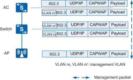
Figure 1 shows the process of forwarding management packets through CAPWAP tunnels.
In Figure 1:
- In the uplink direction (from the AP to the AC): When receiving management packets, the AP encapsulates the packets in CAPWAP packets. The switch tags the packets with VLAN m. The AC decapsulates the CAPWAP packets and removes the tag VLAN m'.
- In the downlink direction (from the AC to the AP): When receiving downstream management packets, the AC encapsulates the packets in CAPWAP packets and tags them with VLAN m'. The switch removes VLAN m from the packets. The AP decapsulates the CAPWAP packets.
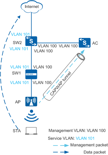
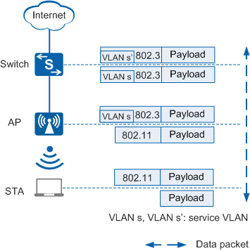
Figure 2 shows the process of directly forwarding service data packets.
In Figure 2, service data packets are not encapsulated in CAPWAP packets.
- In the uplink direction (from the STA to the Internet): When upstream service data packets in 802.11 format are sent from the STA to the AP, the AP converts the packets into 802.3 packets, tags the packets with VLAN s, and forwards the packets to the destination.
- In the downlink direction (from the Internet to the STA): When downstream service data packets in 802.3 format reach the AP (the packets are tagged with VLAN s' by upstream devices), the AP converts the 802.3 packets into 802.11 packets and forwards them to the STA.
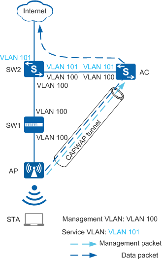
Figure 3 shows the process of forwarding service data packets through CAPWAP tunnels.
In Figure 3, service data packets are encapsulated in CAPWAP packets and transmitted through CAPWAP data tunnels.
- In the uplink direction (from the STA to the Internet): When upstream service data packets in 802.11 format are sent from the STA to the AP, the AP converts the packets into 802.3 packets, tags the packets with VLAN s, and encapsulates them in CAPWAP packets. The upstream switch tags the packets with VLAN m. The AC decapsulates the CAPWAP packets and removes the tag VLAN m' from the packets.
- In the downlink direction (from the Internet to the STA): When downstream service data packets reach the AC, the AC encapsulates the packets in CAPWAP packets, allows the packets carrying VLAN s to pass through, and tags the packets with VLAN m'. The switch removes VLAN m from the packets. The AP decapsulates the CAPWAP packets, removes VLAN s, converts the 802.3 packets into 802.11 packets, and forwards them to the STA.
Management VLAN tag VLAN m is the outer tag of CAPWAP-encapsulated packets. The intermediate devices between the AC and AP can only transparently transmit packets carrying VLAN m and cannot be configured with VLAN s encapsulated in the CAPWAP packets.
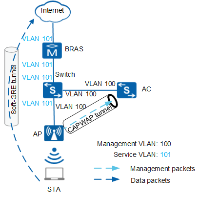
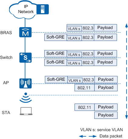
Figure 4 shows the process of forwarding service data packets in soft GRE forwarding mode.
In Figure 4, service data packets are transmitted through a soft GRE tunnel.- When upstream service data packets in 802.11 format are sent from the STA to the AP, the AP converts the packets into 802.3 packets, tags the packets with VLAN s, and encapsulates them in the soft GRE tunnel, and forwards the packets to the BRAS. The BRAS decapsulates the packets using soft GRE and performs unified accounting and authentication.
- The BRAS encapsulates downstream service data packets in the soft GRE tunnel and sends the packets to the AP. The AP decapsulates the packets using soft GRE, converts the 802.3 packets into 802.11 packets, and forwards them to the STA.
Ensure that there is a reachable route between the BRAS and AP so that service data packets can be transmitted through the soft GRE tunnel.

In Figure 5, to implement direct forwarding, ensure that the AP can exchange management VLAN packets with the AC and exchange service VLAN packets with upstream devices.
In Figure 6, to implement tunnel forwarding, ensure that the AP can exchange management VLAN packets with the AC and the AC can exchange service VLAN packets with upstream devices.
In Figure 7, to implement data forwarding through a soft GRE tunnel, ensure that the AP can exchange management VLAN packets with the AC and the AP can exchange service VLAN packets with upstream network devices.