Example for Configuring Wi-Fi Terminal Location
Configuration Process
You need to configure and maintain WLAN features and functions in different profiles. These WLAN profiles include regulatory domain profile, radio profile, VAP profile, AP system profile, AP wired port profile, WIDS profile, WDS profile, and Mesh profile. When configuring WLAN services, you need to set related parameters in the WLAN profiles and bind the profiles to the AP group or APs. Then the configuration is automatically delivered to and takes effect on the APs. WLAN profiles can reference one another; therefore, you need to know the relationships among the profiles before configuring them. For details about the profile relationships and their basic configuration procedure, see WLAN Service Configuration Procedure.
Networking Requirements
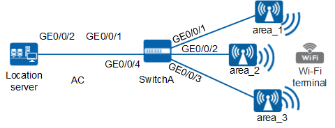
In Figure 1, the AC connects to the APs through a switch on an enterprise network.
The administrator requires that the APs collect Wi-Fi terminal information and report the information to the location server to compute terminal locations so that users can obtain the locations of the Wi-Fi terminals through maps, tables, or reports.
Data preparation
Item |
Data |
|---|---|
Management VLAN for APs |
VLAN100 |
Service VLAN for STAs |
VLAN101 |
DHCP server |
The AC functions as the DHCP server for STAs and APs. |
IP address pool for APs |
10.23.100.3-10.23.100.254/24 |
IP address pool for STAs |
10.23.101.2-10.23.101.254/24 |
AC's source interface |
VLANIF100 |
AP group |
|
Regulatory domain profile |
|
SSID profile |
|
Security profile |
|
VAP profile |
|
Air scan profile |
|
2G radio profile |
|
5G radio profile |
|
Location profile |
|
Configuration Roadmap
The configuration roadmap is as follows:
- Configure basic WLAN services so that users can connect to the internal network through the WLAN.
- Configure Wi-Fi terminal location so that APs can periodically scan channels to collect radio signals and report the collected information to the location server.
Procedure
- Configure the location server (details are not provided here).
- Set the NAC mode to unified on the AC so that users can connect to the network properly.
<HUAWEI> system-view
[HUAWEI] authentication unified-mode

If the NAC mode is changed from traditional to unified, the unified mode takes effect after you save the configuration and restart the device.
- Connect AC and AP.
# Configure the access switch SwitchA. Add GE0/0/1, GE0/0/2, GE0/0/3 and GE0/0/4 on SwitchA to VLAN 100 (management VLAN)
<HUAWEI> system-view
[HUAWEI] sysname SwitchA
[SwitchA] vlan batch 100 101
[SwitchA] interface gigabitethernet 0/0/1
[SwitchA-GigabitEthernet0/0/1] port link-type trunk
[SwitchA-GigabitEthernet0/0/1] port trunk pvid vlan 100
[SwitchA-GigabitEthernet0/0/1] port trunk allow-pass vlan 100
[SwitchA-GigabitEthernet0/0/1] quit
[SwitchA] interface gigabitethernet 0/0/2
[SwitchA-GigabitEthernet0/0/2] port link-type trunk
[SwitchA-GigabitEthernet0/0/2] port trunk pvid vlan 100
[SwitchA-GigabitEthernet0/0/2] port trunk allow-pass vlan 100
[SwitchA-GigabitEthernet0/0/2] quit
[SwitchA] interface gigabitethernet 0/0/3
[SwitchA-GigabitEthernet0/0/3] port link-type trunk
[SwitchA-GigabitEthernet0/0/3] port trunk pvid vlan 100
[SwitchA-GigabitEthernet0/0/3] port trunk allow-pass vlan 100
[SwitchA-GigabitEthernet0/0/3] quit
[SwitchA] interface gigabitethernet 0/0/4
[SwitchA-GigabitEthernet0/0/4] port link-type trunk
[SwitchA-GigabitEthernet0/0/4] port trunk allow-pass vlan 100
[SwitchA-GigabitEthernet0/0/4] quit
# Configure the AC. Add GE0/0/1 to VLAN 100.
<HUAWEI> system-view
[HUAWEI] sysname AC
[AC] vlan batch 100 101
[AC] interface gigabitethernet 0/0/1
[AC-GigabitEthernet0/0/1] port link-type trunk
[AC-GigabitEthernet0/0/1] port trunk allow-pass vlan 100
[AC-GigabitEthernet0/0/1] quit
- Configure the AC to communicate with the location server.
# Add GE0/0/2 that connects the AC and the location server to VLAN 100.
[AC] interface gigabitethernet 0/0/2
[AC-GigabitEthernet0/0/2] port link-type trunk
[AC-GigabitEthernet0/0/2] port trunk pvid vlan 100
[AC-GigabitEthernet0/0/2] port trunk allow-pass vlan 100
[AC-GigabitEthernet0/0/2] quit
- Configure the AC as a DHCP server to allocate IP addresses to STAs and the AP.
# Configure the AC as the DHCP server to allocate an IP address to the AP from the IP address pool on VLANIF 100, and allocate IP addresses to STAs from the IP address pool on VLANIF 101.
Configure the DNS server as required. The common methods are as follows:- In interface address pool scenarios, run the dhcp server dns-list ip-address &<1-8> command in the VLANIF interface view.
- In global address pool scenarios, run the dns-list ip-address &<1-8> command in the IP address pool view.
[AC] dhcp enable
[AC] interface vlanif 100
[AC-Vlanif100] ip address 10.23.100.1 24
[AC-Vlanif100] dhcp select interface
[AC-Vlanif100] quit
[AC] interface vlanif 101
[AC-Vlanif101] ip address 10.23.101.1 24
[AC-Vlanif101] dhcp select interface
[AC-Vlanif101] quit
- Configure the AP to go online.
# Create an AP group and add the AP to the AP group.
[AC] wlan
[AC-wlan-view] ap-group name ap-group1
[AC-wlan-ap-group-ap-group1] quit
# Create a regulatory domain profile, configure the AC country code in the profile, and apply the profile to the AP group.
[AC-wlan-view] regulatory-domain-profile name domain1
[AC-wlan-regulate-domain-domain1] country-code cn
[AC-wlan-regulate-domain-domain1] quit
[AC-wlan-view] ap-group name ap-group1
[AC-wlan-ap-group-ap-group1] regulatory-domain-profile domain1
Warning: Modifying the country code will clear channel, power and antenna gain configurations of the radio and reset the AP. Continue?[Y/N]:y
[AC-wlan-ap-group-ap-group1] quit
[AC-wlan-view] quit
# Configure the AC's source interface.
[AC] capwap source interface vlanif 100
# Import the AP offline on the AC and add the AP to AP group ap-group1. Configure a name for the AP based on the AP's deployment location, so that you can know where the AP is deployed from its name. For example, name the AP area_1 if it is deployed in Area 1. The default AP authentication mode is MAC address authentication. If the default settings are retained, you do not need to run the ap auth-mode mac-auth command.
In this example, the AP5030DN is used and has two radios: radio 0 (2.4 GHz radio) and radio 1 (5 GHz radio).
[AC] wlan
[AC-wlan-view] ap auth-mode mac-auth
[AC-wlan-view] ap-id 0 ap-mac 60de-4476-e360
[AC-wlan-ap-0] ap-name area_1
[AC-wlan-ap-0] ap-group ap-group1
Warning: This operation may cause AP reset. If the country code changes, it will clear channel, power and antenna gain configuration s of the radio, Whether to continue? [Y/N]:y
[AC-wlan-ap-0] quit
[AC-wlan-view] ap-id 1 ap-mac dcd2-fc9d-0bb0
[AC-wlan-ap-1] ap-name area_2
[AC-wlan-ap-1] ap-group ap-group1
Warning: This operation may cause AP reset. If the country code changes, it will clear channel, power and antenna gain configuration s of the radio, Whether to continue? [Y/N]:y
[AC-wlan-ap-1] quit
[AC-wlan-view] ap-id 2 ap-mac dcd2-fc04-b500
[AC-wlan-ap-2] ap-name area_3
[AC-wlan-ap-2] ap-group ap-group1
Warning: This operation may cause AP reset. If the country code changes, it will clear channel, power and antenna gain configuration s of the radio, Whether to continue? [Y/N]:y
[AC-wlan-ap-2] quit
# After the AP is powered on, run the display ap all command to check the AP state. If the State field is displayed as nor, the AP goes online normally.
[AC-wlan-view] display ap all
Total AP information:
nor  : normal          [3]
ExtraInfo : Extra information
P     : insufficient power supply
-------------------------------------------------------------------------------------
ID   MAC            Name   Group     IP            Type            State STA Uptime
-------------------------------------------------------------------------------------
0    60de-4476-e360 area_1 ap-group1 10.23.100.254 AP5030DN        nor   0   25S
1    dcd2-fc9d-0bb0 area_2 ap-group1 10.23.100.253 AP5030DN        nor   0   20S
2    dcd2-fc04-b500 area_3 ap-group1 10.23.100.252 AP5030DN        nor   0   10S
-------------------------------------------------------------------------------------
Total: 3
- Configure WLAN service parameters.# Create security profile wlan-security and set the security policy in the profile.
In this example, the security policy is set to WPA2+PSK+AES and password to a1234567. In actual situations, the security policy must be configured according to service requirements.
[AC-wlan-view] security-profile name wlan-security
[AC-wlan-sec-prof-wlan-security] security wpa2 psk pass-phrase a1234567 aes
[AC-wlan-sec-prof-wlan-security] quit
# Create SSID profile wlan-ssid and set the SSID name to wlan-net.
[AC-wlan-view] ssid-profile name wlan-ssid
[AC-wlan-ssid-prof-wlan-ssid] ssid wlan-net
[AC-wlan-ssid-prof-wlan-ssid] quit
# Create VAP profile wlan-vap, set the data forwarding mode and service VLAN, and apply the security profile and SSID profile to the VAP profile.
[AC-wlan-view] vap-profile name wlan-vap
[AC-wlan-vap-prof-wlan-vap] forward-mode tunnel
[AC-wlan-vap-prof-wlan-vap] service-vlan vlan-id 101
[AC-wlan-vap-prof-wlan-vap] security-profile wlan-security
[AC-wlan-vap-prof-wlan-vap] ssid-profile wlan-ssid
[AC-wlan-vap-prof-wlan-vap] quit
# Bind VAP profile wlan-vap to the AP group and apply the profile to radio 0 and radio 1 of the AP.
[AC-wlan-view] ap-group name ap-group1
[AC-wlan-ap-group-ap-group1] vap-profile wlan-vap wlan 1 radio all
[AC-wlan-ap-group-ap-group1] quit
- Configure the WLAN air scan function.# Create an air scan profile named wlan-air-scan and configure an air scan channel set.
[AC-wlan-view] air-scan-profile name wlan-air-scan
[AC-wlan-air-scan-prof-wlan-air-scan] scan-channel-set country-channel
[AC-wlan-air-scan-prof-wlan-air-scan] quit
# Create a 2G radio profile named wlan-radio-2g and bind the air scan profile wlan-air-scan to the 2G radio profile.[AC-wlan-view] radio-2g-profile name wlan-radio-2g [AC-wlan-radio-2g-prof-wlan-radio-2g] air-scan-profile wlan-air-scan [AC-wlan-radio-2g-prof-wlan-radio-2g] quit
# Create a 5G radio profile named wlan-radio-5g and bind the air scan profile wlan-air-scan to the 5G radio profile.[AC-wlan-view] radio-5g-profile name wlan-radio-5g [AC-wlan-radio-5g-prof-wlan-radio-5g] air-scan-profile wlan-air-scan [AC-wlan-radio-5g-prof-wlan-radio-5g] quit
# Configure an AP group and bind the radio profile to the AP group.[AC-wlan-view] ap-group name ap-group1 [AC-wlan-ap-group-ap-group1] radio-2g-profile wlan-radio-2g radio 0 [AC-wlan-ap-group-ap-group1] radio-5g-profile wlan-radio-5g radio 1 [AC-wlan-ap-group-ap-group1] quit - Configure the Wi-Fi terminal location function.# Create a location profile named wlan-location. Enable the Wi-Fi terminal location function. Configure the target and port number to report location information.
[AC-wlan-view] location-profile name wlan-location
[AC-wlan-location-prof-wlan-location] private mu-enable
[AC-wlan-location-prof-wlan-location] private server ip-address 10.23.100.2 port 32180 via-ac ac-port 10001
[AC-wlan-location-prof-wlan-location] source ip-address 10.23.100.1
[AC-wlan-location-prof-wlan-location] quit
# Configure an AP group and bind the location profile to the AP group.[AC-wlan-view] ap-group name ap-group1 [AC-wlan-ap-group-ap-group1] location-profile wlan-location radio all [AC-wlan-ap-group-ap-group1] quit
- Verify the configuration.
The AC automatically delivers WLAN service configuration to the AP. After the service configuration is complete, run the display vap ssid wlan-net command. If Status in the command output is displayed as ON, the VAPs have been successfully created on AP radios.
[AC-wlan-view] display vap ssid wlan-net
WID : WLAN ID
------------------------------------------------------------------------------------
AP ID AP name        RfID WID  BSSID          Status  Auth type     STA   SSID
------------------------------------------------------------------------------------
0     area_1         0    1    60DE-4476-E360 ON      WPA2-PSK      1     wlan-net
0     area_1         1    1    60DE-4476-E370 ON      WPA2-PSK      0     wlan-net
1     area_2         0    1    DCD2-FC9D-0BB0 ON      WPA2-PSK      0     wlan-net
1     area_2         1    1    DCD2-FC9D-0BC0 ON      WPA2-PSK      0     wlan-net
2     area_3         0    1    DCD2-FC04-B500 ON      WPA2-PSK      0     wlan-net
2     area_3         1    1    DCD2-FC04-B510 ON      WPA2-PSK      0     wlan-net
------------------------------------------------------------------------------------
Total: 6
Configuration Files
SwitchA configuration file
#
sysname SwitchA
#
vlan batch 100
#
interface GigabitEthernet0/0/1
 port link-type trunk
 port trunk pvid vlan 100
 port trunk allow-pass vlan 100
#
interface GigabitEthernet0/0/2
 port link-type trunk
 port trunk pvid vlan 100
 port trunk allow-pass vlan 100
#
interface GigabitEthernet0/0/3
 port link-type trunk
 port trunk pvid vlan 100
 port trunk allow-pass vlan 100
#
interface GigabitEthernet0/0/4
 port link-type trunk
 port trunk allow-pass vlan 100
#
return
AC configuration file
#
 sysname AC
#
vlan batch 100 to 101
#
dhcp enable
#
interface Vlanif100
 ip address 10.23.100.1 255.255.255.0
 dhcp select interface
#
interface Vlanif101
 ip address 10.23.101.1 255.255.255.0
 dhcp select interface
#
interface GigabitEthernet0/0/1
 port link-type trunk
 port trunk allow-pass vlan 100
#
interface GigabitEthernet0/0/2
 port link-type trunk
 port trunk pvid vlan 100
 port trunk allow-pass vlan 100
#
capwap source interface vlanif100
#
wlan
 security-profile name wlan-security
  security wpa2 psk pass-phrase %^%#_b"h2cpaO$9bZ-;`-_;CN5)k,_\UP3[!AJE6Vtg3%^%# aes
 ssid-profile name wlan-ssid
  ssid wlan-net
 vap-profile name wlan-vap
  forward-mode tunnel
  service-vlan vlan-id 101
  ssid-profile wlan-ssid
  security-profile wlan-security
 location-profile name wlan-location
  private mu-enable
  private server ip-address 10.23.100.2 port 32180 via-ac ac-port 10001
  source ip-address 10.23.100.1
 regulatory-domain-profile name domain1
 air-scan-profile name wlan-air-scan
 radio-2g-profile name wlan-radio-2g
  air-scan-profile wlan-air-scan
 radio-5g-profile name wlan-radio-5g
  air-scan-profile wlan-air-scan
 ap-group name ap-group1
  regulatory-domain-profile domain1
  location-profile wlan-location radio all
  radio 0
   radio-2g-profile wlan-radio-2g
   vap-profile wlan-vap wlan 1
  radio 1
   radio-5g-profile wlan-radio-5g
   vap-profile wlan-vap wlan 1
 ap-id 0 type-id 19 ap-mac 60de-4476-e360 ap-sn 210235419610CB002287
  ap-name area_1
  ap-group ap-group1
 ap-id 1 type-id 19 ap-mac dcd2-fc9d-0bb0 ap-sn 210235555310CC000094
  ap-name area_2
  ap-group ap-group1
 ap-id 2 type-id 19 ap-mac dcd2-fc04-b500 ap-sn 210235554710CB000042
  ap-name area_3
  ap-group ap-group1
#
return