Example for Configuring Vehicle-Ground Fast Link Handover
Networking Requirements
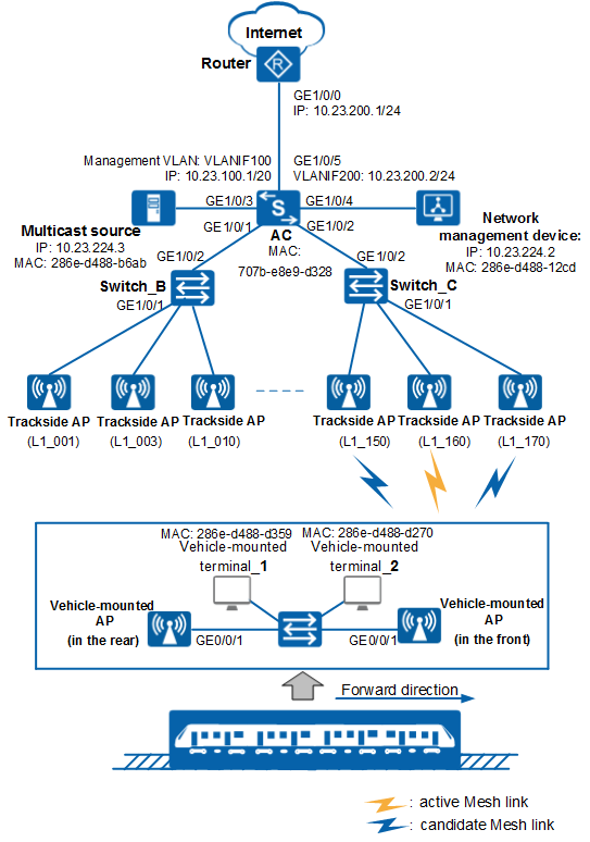
A rail transportation enterprise needs to implement vehicle-ground communications through WLAN technology to reduce network deployment costs and better serve passengers. By leveraging the WLAN, the enterprise expects that multicast servers on the ground network can deliver multimedia information services to passengers. As shown in Figure 1, trackside APs are deployed along rail line 1 of the enterprise. The AC on the ground network communicates with the trackside APs in wired mode at Layer 2. A vehicle-mounted AP is deployed in the front and rear of a train. When the train is running, only the vehicle-mounted AP in the front works. The vehicle-mounted AP in the rear is in dormancy state. After the train arrives at the destination, it switches the forward direction. The working vehicle-mounted AP changes accordingly. The vehicle-mounted AP sets up wireless links with the trackside APs, allowing the multicast servers on the ground network to offer passengers multimedia information services.
Configuration Roadmap
- Configure the ground network to enable Layer 2 communications between trackside APs and the AC.
- Configure multicast services on ground network devices to enable proper multicast data forwarding on the ground network.
- Configure vehicle-ground fast link handover on trackside and vehicle-mounted APs so that the vehicle-mounted AP can set up Mesh connections with the trackside APs.
- Configure the vehicle-mounted network to enable intra-network data communications.

- This example uses Huawei AP9131DNs (Fit APs) as the trackside APs and AP9131DNs (Fat APs) as the vehicle-mounted APs.
- Switches and routers used in this example are all Huawei products.
AP |
Model |
MAC |
|---|---|---|
Trackside AP (L1_001) |
AP9131DN |
0046-4b59-1d10 |
Trackside AP (L1_003) |
AP9131DN |
0046-4b59-1d20 |
Trackside AP (L1_010) |
AP9131DN |
0046-4b59-1d30 |
Trackside AP (L1_150) |
AP9131DN |
0046-4b59-1d40 |
Trackside AP (L1_160) |
AP9131DN |
0046-4b59-1d50 |
Trackside AP (L1_170) |
AP9131DN |
0046-4b59-1d60 |
…… |
||
Vehicle-mounted AP (in the front) |
AP9131DN |
0046-4b59-2e10 |
Vehicle-mounted AP (in the rear) |
AP9131DN |
0046-4b59-2e20 |
…… |
||
Item |
Data |
|---|---|
Management VLAN |
VLAN 100 |
Multicast service VLAN |
VLAN 101 |
Gateway address |
IP address of VLANIF 101 on AC: 10.23.224.1/24 |
DHCP server |
The AC functions as a DHCP server to allocate IP addresses to trackside APs and vehicle-mounted terminals. |
IP address pool for APs |
10.23.100.2-10.23.100.254/24 |
IP address pool for vehicle-mounted terminals |
10.23.224.4-10.23.224.254/24 |
AC's source interface address |
VLANIF 100: 10.23.100.1/24 |
AP group to which trackside APs belong |
Name: mesh-mpp |
ID of trackside APs |
|
Security profile |
|
Mesh profile |
Trackside APs:
Vehicle-mounted APs:
|
Mesh handover profile |
Trackside APs:
Vehicle-mounted APs:
|
Mesh whitelist on trackside APs |
Name: whitelist01 Add MAC addresses of all vehicle-mounted APs on trains running on the rail to the whitelist according to actual situations. |
Mesh whitelist on vehicle-mounted APs |
Name: whitelist01 Add MAC addresses of all trackside APs along the rail line to the whitelist according to actual situations. |
MAC address of the proxied ground device |
|
MAC address of the proxied vehicle-mounted device |
|
Multicast group |
225.1.1.1-225.1.1.3 |
Configuration Notes
- No ACK mechanism is provided for multicast packet transmission on air interfaces. In addition, wireless links are unstable. To ensure stable transmission of multicast packets, they are usually sent at low rates. If a large number of such multicast packets are sent from the network side, the air interfaces may be congested. You are advised to configure multicast packet suppression to reduce impact of a large number of low-rate multicast packets on the wireless network. Exercise caution when configuring the rate limit; otherwise, the multicast services may be affected.
- In direct forwarding mode, you are advised to configure multicast packet suppression on switch interfaces connected to APs.
- In tunnel forwarding mode, you are advised to configure multicast packet suppression in traffic profiles of the AC.
Configure port isolation on the interfaces of the device directly connected to APs. If port isolation is not configured and direct forwarding is used, a large number of unnecessary broadcast packets may be generated in the VLAN, blocking the network and degrading user experience.
In tunnel forwarding mode, the management VLAN and service VLAN cannot be the same. Only packets from the management VLAN are transmitted between the AC and APs. Packets from the service VLAN are not allowed between the AC and APs.
Procedure
- Configure ground network devices.
- Configure an IP address for GE1/0/0 on the router and configure routes to the internal network segment, with the next hop address 10.23.200.2.
<Huawei> system-view
[Huawei] sysname Router
[Router] interface gigabitethernet 1/0/0
[Router-GigabitEthernet1/0/0] ip address 10.23.200.1 24
[Router-GigabitEthernet1/0/0] quit
[Router] ip route-static 10.23.224.0 20 10.23.200.2
[Router] ip route-static 10.23.100.0 20 10.23.200.2
You can configure routes to external networks and the NAT function on the egress router according to service requirements to ensure normal communications between internal and external networks.
- Configure Switch_B and Switch_C to enable Layer 2 communications between trackside APs and the ground network.# On Switch_B, create VLAN 100 and VLAN 101, configure GE0/0/2 and GE0/0/1 to allow packets from VLAN 100 and VLAN 101 to pass through, and set the PVID of GE0/0/1 to VLAN 100 (management VLAN for trackside APs).
Configure other interfaces connected to trackside APs on Switch_B according to GE0/0/1: allow packets from VLAN 100 and VLAN 101 to pass through and set their PVIDs to VLAN 100.
<HUAWEI> system-view
[HUAWEI] sysname Switch_B
[Switch_B] vlan batch 100 101
[Switch_B] interface gigabitEthernet 0/0/2
[Switch_B-GigabitEthernet0/0/2] port link-type trunk
[Switch_B-GigabitEthernet0/0/2] port trunk allow-pass vlan 100 101
[Switch_B-GigabitEthernet0/0/2] quit
[Switch_B] interface gigabitEthernet 0/0/1
[Switch_B-GigabitEthernet0/0/1] port link-type trunk
[Switch_B-GigabitEthernet0/0/1] port trunk pvid vlan 100
[Switch_B-GigabitEthernet0/0/1] port trunk allow-pass vlan 100 101
[Switch_B-GigabitEthernet0/0/1] quit
# On Switch_C, create VLAN 100 and VLAN 101, and configure GE0/0/2 and GE0/0/1 to allow packets from VLAN 100 and VLAN 101 to pass through, and set the PVID of GE0/0/1 to VLAN 100. Configure other interfaces connected to trackside APs on Switch_C according to GE0/0/1: allow packets from VLAN 100 and VLAN 101 to pass through and set their PVIDs to VLAN 100.
<HUAWEI> system-view
[HUAWEI] sysname Switch_C
[Switch_C] vlan batch 100 101
[Switch_C] interface gigabitEthernet 0/0/2
[Switch_C-GigabitEthernet0/0/2] port link-type trunk
[Switch_C-GigabitEthernet0/0/2] port trunk allow-pass vlan 100 101
[Switch_C-GigabitEthernet0/0/2] quit
[Switch_C] interface gigabitEthernet 0/0/1
[Switch_C-GigabitEthernet0/0/1] port link-type trunk
[Switch_C-GigabitEthernet0/0/1] port trunk pvid vlan 100
[Switch_C-GigabitEthernet0/0/1] port trunk allow-pass vlan 100 101
[Switch_C-GigabitEthernet0/0/1] quit
- Enable Layer 2 multicast on AC, Switch_B, and Switch_C to allow them to properly forward multicast data.
# Enable IGMP snooping globally on AC.
[AC] igmp-snooping enable
# Enable IGMP snooping in VLAN 101 on AC.
[AC] vlan 101
[AC-vlan101] igmp-snooping enable
[AC-vlan101] quit
# Configure multicast group filter policies on AC.
[AC] acl 2000
[AC-acl-basic-2000] rule permit source 225.1.1.1 0
[AC-acl-basic-2000] rule permit source 225.1.1.2 0
[AC-acl-basic-2000] rule permit source 225.1.1.3 0
[AC-acl-basic-2000] quit
# Apply the multicast group filter policies in VLAN 101 on AC.
[AC] vlan 101
[AC-vlan101] igmp-snooping group-policy 2000
[AC-vlan101] quit
Complete multicast configuration on Switch_B and Switch_C according to the multicast configuration procedure of AC.
# Configure the fast leave function on Switch_B and Switch_C.
If trackside APs are directly connected to the switches and Layer 2 multicast is configured, enabling the fast leave function improves the quality of multicast services. If the trackside APs are not directly connected to the switches or Layer 3 multicast is configured, you cannot configure the fast leave function because this function may interrupt multicast services.
[Switch_B] vlan 101
[Switch_B-vlan101] igmp-snooping prompt-leave group-policy 2000
[Switch_C] vlan 101
[Switch_C-vlan101] igmp-snooping prompt-leave group-policy 2000
- Configure the AP group, country code, and AC's source interface.
# Create the AP group mesh-mpp and add trackside APs that require the same configuration to the group.
[AC] wlan
[AC-wlan-view] ap-group name mesh-mpp
[AC-wlan-ap-group-mesh-mpp] quit
# Create a regulatory domain profile, configure the AC country code in the profile, and apply the profile to the AP group.
[AC-wlan-view] regulatory-domain-profile name domain1
[AC-wlan-regulate-domain-domain1] country-code cn
[AC-wlan-regulate-domain-domain1] quit
[AC-wlan-view] ap-group name mesh-mpp
[AC-wlan-ap-group-mesh-mpp] regulatory-domain-profile domain1
Warning: Modifying the country code will clear channel, power and antenna gain configurations of the radio and reset the AP. Continue?[Y/N]:y
[AC-wlan-ap-group-mesh-mpp] quit
[AC-wlan-view] quit
# Configure the AC's source interface.
[AC] capwap source interface vlanif 100
# Add trackside APs to the AP group mesh-mpp. The default AP authentication mode is MAC address authentication. If the default settings are retained, you do not need to run the ap auth-mode mac-auth command.
[AC] wlan
[AC-wlan-view] ap auth-mode mac-auth
[AC-wlan-view] ap-id 1 ap-mac 0046-4b59-1d10
[AC-wlan-ap-1] ap-name L1_001
[AC-wlan-ap-1] ap-group mesh-mpp
Warning: This operation may cause AP reset. If the country code changes, it will clear channel, power and antenna gain configuration s of the radio, Whether to continue? [Y/N]:y
[AC-wlan-ap-1] quit
[AC-wlan-view] ap-id 2 ap-mac 0046-4b59-1d20
[AC-wlan-ap-2] ap-name L1_003
[AC-wlan-ap-2] ap-group mesh-mpp
Warning: This operation may cause AP reset. If the country code changes, it will clear channel, power and antenna gain configuration s of the radio, Whether to continue? [Y/N]:y
[AC-wlan-ap-2] quit
[AC-wlan-view] ap-id 3 ap-mac 0046-4b59-1d30
[AC-wlan-ap-3] ap-name L1_010
[AC-wlan-ap-3] ap-group mesh-mpp
Warning: This operation may cause AP reset. If the country code changes, it will clear channel, power and antenna gain configuration s of the radio, Whether to continue? [Y/N]:y
[AC-wlan-ap-3] quit
[AC-wlan-view] ap-id 101 ap-mac 0046-4b59-1d40
[AC-wlan-ap-101] ap-name L1_150
[AC-wlan-ap-101] ap-group mesh-mpp
Warning: This operation may cause AP reset. If the country code changes, it will clear channel, power and antenna gain configuration s of the radio, Whether to continue? [Y/N]:y
[AC-wlan-ap-101] quit
[AC-wlan-view] ap-id 102 ap-mac 0046-4b59-1d50
[AC-wlan-ap-102] ap-name L1_160
[AC-wlan-ap-102] ap-group mesh-mpp
Warning: This operation may cause AP reset. If the country code changes, it will clear channel, power and antenna gain configuration s of the radio, Whether to continue? [Y/N]:y
[AC-wlan-ap-102] quit
[AC-wlan-view] ap-id 103 ap-mac 0046-4b59-1d60
[AC-wlan-ap-103] ap-name L1_170
[AC-wlan-ap-103] ap-group mesh-mpp
Warning: This operation may cause AP reset. If the country code changes, it will clear channel, power and antenna gain configuration s of the radio, Whether to continue? [Y/N]:y
[AC-wlan-ap-103] quit
- Configure Mesh parameters.
# Create the Mesh whitelist whitelist01 and add MAC addresses of vehicle-mounted APs to the Mesh whitelist.
[AC-wlan-view] mesh-whitelist name whitelist01
[AC-wlan-mesh-whitelist-whitelist01] peer-ap mac 0046-4b59-2e10
[AC-wlan-mesh-whitelist-whitelist01] peer-ap mac 0046-4b59-2e20
[AC-wlan-mesh-whitelist-whitelist01] quit
Add MAC addresses of vehicle-mounted APs on other trains to the Mesh whitelist whitelist01 according to the preceding procedure.
# Configure the security profile sp01 used by Mesh links. The Mesh network supports only the security policy WPA2+PSK+AES.
[AC-wlan-view] security-profile name sp01
[AC-wlan-sec-prof-sp01] security wpa2 psk pass-phrase a1234567 aes
[AC-wlan-sec-prof-sp01] quit
# Configure the Mesh role. Set the Mesh role of trackside APs to mesh-portal through the AP system profile.
[AC-wlan-view] ap-system-profile name mesh-sys
[AC-wlan-ap-system-prof-mesh-sys] mesh-role mesh-portal
[AC-wlan-ap-system-prof-mesh-sys] quit
# Configure the Mesh handover profile hand-over and enable the location-based fast link handover algorithm.
[AC-wlan-view] mesh-handover-profile name hand-over
[AC-wlan-mesh-handover-hand-over] location-based-algorithm enable
[AC-wlan-mesh-handover-hand-over] quit
# Configure the Mesh profile. Set the ID of the Mesh network to mesh-net and apply the security profile and Mesh handover profile.
[AC-wlan-view] mesh-profile name mesh-net
[AC-wlan-mesh-prof-mesh-net] mesh-id mesh-net
[AC-wlan-mesh-prof-mesh-net] security-profile sp01
[AC-wlan-mesh-prof-mesh-net] mesh-handover-profile hand-over
[AC-wlan-mesh-prof-mesh-net] quit
- Configure an IP address for GE1/0/0 on the router and configure routes to the internal network segment, with the next hop address 10.23.200.2.
- Configure vehicle-mounted network devices.
For the configurations for the vehicle-mounted APs on the vehicle head and tail, see Configuration Guide - Vehicle-Ground Fast Link Handover in Fat AP & Cloud AP Product Documentation or Fat AP & Cloud AP V200R007C20 Product Documentation.
- Verify the configuration.
# After vehicle-ground fast link handover configuration is complete, run the display wlan mesh link all command on the AC to view Mesh connections between trackside and vehicle-mounted APs.
<AC> display wlan mesh link all
Rf   : radio ID             Dis  : coverage distance(100m)
Ch   : channel              Per  : drop percent(%)
TSNR : total SNR(dB)        P-   : peer
Mesh : Mesh mode            Re   : retry ratio(%)
RSSI : RSSI(dBm)            MaxR : max RSSI(dBm)
----------------------------------------------------------------------------------------------------------------------------------
APName          P-APName        P-APMAC         Rf Dis   Ch      Mesh    P-Status        RSSI  MaxR  Per  Re   TSNR  SNR(Ch0~3:dB)
Tx(Mbps)    Rx(Mbps)
----------------------------------------------------------------------------------------------------------------------------------
L1_001          AP              0046-4b59-2e10  1  3     157     portal  -               -51   -38   0    0    47    39/47/-/-
192         192
L1_003          AP              0046-4b59-2e10  1  3     157     portal  -               -59   -7    0    0    50    19/14/37/-
192         192
L1_010          AP              0046-4b59-2e10  1  3     157     portal  -               -45   -33   0    0    37    20/17/17/-
192         192
L1_150          AP              0046-4b59-2e10  1  3     157     portal  -               -54   -39   0    0    46    34/43/-/-
192         192
L1_160          AP              0046-4b59-2e10  1  3     157     portal  -               -52   -7    0    0    32    21/18/35/-
192         192
L1_170          AP              0046-4b59-2e10  1  3     157     portal  -               -42   -33   0    0    29    26/14/19/-
192         192
----------------------------------------------------------------------------------------------------------------------------------
Total: 6
# Run the display mesh-neighbor-rssi command on the AC to view RSSI information of trackside APs.
[AC-wlan-view] display mesh-neighbor-rssi
AP name/MAC/Radio/Location-ID  Neighbor AP/MAC/Location-ID  RSSI  Update Time
------------------------------------------------------------------------------
L1_001/0046-4b59-1d10/1/1        -/00bc-da3f-e900/-           -44   18:08:21
L1_003/0046-4b59-1d20/1/3        -/00bc-da3f-e900/-           -50   18:08:20
L1_010/0046-4b59-1d30/1/10       -/00bc-da3f-e900/-           -28   18:08:21
L1_150/0046-4b59-1d40/1/150      -/0046-4b59-2e10/-           -43   18:08:20
L1_160/0046-4b59-1d50/1/160      -/0046-4b59-2e10/-           -47   18:08:21
L1_170/0046-4b59-1d60/1/170      -/0046-4b59-2e10/-           -38   18:08:21
------------------------------------------------------------------------------
Total: 6
Configuration Files
Ground network devices
Router configuration file
#
sysname Router
#
interface GigabitEthernet1/0/0
 ip address 10.23.200.1 255.255.255.0
#
ip route-static 10.23.100.0 255.255.240.0 10.23.200.2
ip route-static 10.23.224.0 255.255.240.0 10.23.200.2
#
return
Switch_B configuration file
#
sysname Switch_B
#
 vlan batch 100 to 101
#
igmp-snooping enable
#
vlan 101
 igmp-snooping enable
 igmp-snooping group-policy 2000
 igmp-snooping prompt-leave group-policy 2000
#
acl number 2000
 rule 5 permit source 225.1.1.1 0
 rule 10 permit source 225.1.1.2 0
 rule 15 permit source 225.1.1.3 0
#
interface GigabitEthernet0/0/1
 port link-type trunk
 port trunk pvid vlan 100
 port trunk allow-pass vlan 100 to 101
#
interface GigabitEthernet0/0/2
 port link-type trunk
 port trunk allow-pass vlan 100 to 101
#
interface GigabitEthernet0/0/3
 port link-type trunk
 port trunk pvid vlan 100
 port trunk allow-pass vlan 100 to 101
#
interface GigabitEthernet0/0/4
 port link-type trunk
 port trunk pvid vlan 100
 port trunk allow-pass vlan 100 to 101
#
return
Switch_C configuration file
#
sysname Switch_C
#
 vlan batch 100 to 101
#
igmp-snooping enable
#
vlan 101
 igmp-snooping enable
 igmp-snooping group-policy 2000
 igmp-snooping prompt-leave group-policy 2000
#
acl number 2000
 rule 5 permit source 225.1.1.1 0
 rule 10 permit source 225.1.1.2 0
 rule 15 permit source 225.1.1.3 0
#
interface GigabitEthernet0/0/1
 port link-type trunk
 port trunk pvid vlan 100
 port trunk allow-pass vlan 100 to 101
#
interface GigabitEthernet0/0/2
 port link-type trunk
 port trunk allow-pass vlan 100 to 101
#
interface GigabitEthernet0/0/3
 port link-type trunk
 port trunk pvid vlan 100
 port trunk allow-pass vlan 100 to 101
#
interface GigabitEthernet0/0/4
 port link-type trunk
 port trunk pvid vlan 100
 port trunk allow-pass vlan 100 to 101
#
return
AC configuration file
#
sysname AC
#
vlan batch 100 to 101 200
#
igmp-snooping enable
#
dhcp enable
#
acl number 2000
 rule 5 permit source 225.1.1.1 0
 rule 10 permit source 225.1.1.2 0
 rule 15 permit source 225.1.1.3 0
#
vlan 101
 igmp-snooping enable
 igmp-snooping group-policy 2000
#
interface Vlanif100
 ip address 10.23.100.1 255.255.240.0
 dhcp select interface
#
interface Vlanif101
 ip address 10.23.224.1 255.255.240.0
 dhcp select interface
 dhcp server excluded-ip-address 10.23.224.2 10.23.224.3
#
interface Vlanif200
 ip address 10.23.200.2 255.255.255.0
#
interface GigabitEthernet0/0/1
 port link-type trunk
 port trunk allow-pass vlan 100 to 101
#
interface GigabitEthernet0/0/2
 port link-type trunk
 port trunk allow-pass vlan 100 to 101
#
interface GigabitEthernet0/0/3
 port link-type trunk
 port trunk pvid vlan 101
 port trunk allow-pass vlan 101
#
interface GigabitEthernet0/0/4
 port link-type trunk
 port trunk pvid vlan 101
 port trunk allow-pass vlan 101
#
interface GigabitEthernet0/0/5
 port link-type trunk
 port trunk pvid vlan 200
 port trunk allow-pass vlan 200
#
ip route-static 0.0.0.0 0.0.0.0 10.23.200.1
#
capwap source interface vlanif100
#
wlan
 security-profile name sp01
  security wpa2 psk pass-phrase %^%#g^Rs#om$z!uIXX;5P9W.#&g;"F4a6[$CJ$w2s]bhH%^%# aes
 mesh-handover-profile name hand-over
  location-based-algorithm enable
 mesh-whitelist-profile name whitelist01
  peer-ap mac 0046-4b59-2e10
  peer-ap mac 0046-4b59-2e20
 mesh-profile name mesh-net
  mesh-handover-profile hand-over
  security-profile sp01
  mesh-id mesh-net
 regulatory-domain-profile name domain1
 ap-system-profile name mesh-sys
  mesh-role mesh-portal
 wired-port-profile name wired-port
  vlan tagged 101
 ap-group name mesh-mpp
  ap-system-profile mesh-sys
  wired-port-profile wired-port gigabitethernet 0
  regulatory-domain-profile domain1
  radio 1
   mesh-profile mesh-net
   mesh-whitelist-profile whitelist01
   channel 40mhz-plus 157
 ap-id 1 ap-mac 0046-4b59-1d10
  ap-name L1_001
  ap-group mesh-mpp
 ap-id 2 ap-mac 0046-4b59-1d20
  ap-name L1_003
  ap-group mesh-mpp
 ap-id 3 ap-mac 0046-4b59-1d30
  ap-name L1_010
  ap-group mesh-mpp
 ap-id 101 ap-mac 0046-4b59-1d40
  ap-name L1_150
  ap-group mesh-mpp
 ap-id 102 ap-mac 0046-4b59-1d50
  ap-name L1_160
  ap-group mesh-mpp
 ap-id 103 ap-mac 0046-4b59-1d60
  ap-name L1_170
  ap-group mesh-mpp
#
return
Vehicle-mounted network devices
N/A