Example for Configuring Dual-Link Cold Backup Globally (Global Configuration Mode)
Configuration Process
You need to configure and maintain WLAN features and functions in different profiles. These WLAN profiles include regulatory domain profile, radio profile, VAP profile, AP system profile, AP wired port profile, WIDS profile, WDS profile, and Mesh profile. When configuring WLAN services, you need to set related parameters in the WLAN profiles and bind the profiles to the AP group or APs. Then the configuration is automatically delivered to and takes effect on the APs. WLAN profiles can reference one another; therefore, you need to know the relationships among the profiles before configuring them. For details about the profile relationships and their basic configuration procedure, see WLAN Service Configuration Procedure.
Networking Requirements
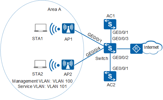
An enterprise uses two APs to deploy WLAN area A to provide WLAN services. As shown in Figure 1, AP1 and AP2 in area A are directly connected to the switch, the enterprise deploys two ACs in bypass mode, and the switch connects to the Internet through the egress route. The enterprise requires that dual-link backup be used to improve data transmission reliability.
Configuration Roadmap
- Set up connections between the AC1, AC2, and other network devices. Configure the switch as a DHCP server to allocate IP addresses to APs and STAs.
- Configure AC1 as the active AC and configure basic WLAN services on AC1.
- Configure AC2 as the standby AC and configure basic WLAN services on AC2. Ensure that service configurations on AC1 and AC2 are the same.
- Configure dual-link backup on the active AC first and then on the standby AC. When dual-link backup is enabled, all APs are restarted. After dual-link backup configurations are complete, the standby AC replaces the active AC to manage APs if the CAPWAP tunnel between the active AC and APs is disconnected.
Item |
Data |
|---|---|
Management VLAN for APs |
VLAN 100 |
Service VLAN for STAs |
VLAN 101 |
DHCP server |
Switch functions as the DHCP server for the APs and STAs. STAs' gateway: 10.23.101.1/24 APs' gateway: 10.23.100.1/24 |
IP address pool for APs |
10.23.100.4-10.23.100.254/24 |
IP address pool for STAs |
10.23.101.2-10.23.101.254/24 |
AC's source interface |
VLANIF 100 |
Active AC |
AC1 Local priority: 0 |
Standby AC |
AC2 Local priority: 1 |
Management IP address of AC1 |
VLANIF 100: 10.23.100.2/24 |
Management IP address of AC2 |
VLANIF 100: 10.23.100.3/24 |
AP group |
|
SSID profile |
|
Security profile |
|
VAP profile |
|
Configuration Notes
- No ACK mechanism is provided for multicast packet transmission on air interfaces. In addition, wireless links are unstable. To ensure stable transmission of multicast packets, they are usually sent at low rates. If a large number of such multicast packets are sent from the network side, the air interfaces may be congested. You are advised to configure multicast packet suppression to reduce impact of a large number of low-rate multicast packets on the wireless network. Exercise caution when configuring the rate limit; otherwise, the multicast services may be affected.
- In direct forwarding mode, you are advised to configure multicast packet suppression on switch interfaces connected to APs.
- In tunnel forwarding mode, you are advised to configure multicast packet suppression in traffic profiles of the AC.
Configure port isolation on the interfaces of the device directly connected to APs. If port isolation is not configured and direct forwarding is used, a large number of unnecessary broadcast packets may be generated in the VLAN, blocking the network and degrading user experience.
In tunnel forwarding mode, the management VLAN and service VLAN cannot be the same. Only packets from the management VLAN are transmitted between the AC and APs. Packets from the service VLAN are not allowed between the AC and APs.
Dual-link backup cannot back up DHCP information. When the AC functions as the DHCP server to assign IP addresses to APs and STAs, APs and STAs need to re-obtain IP addresses if the active AC is faulty. It is recommended that the switch function as the DHCP server. If the AC must be used as the DHCP server, configure address pools containing different IP addresses on the active and standby ACs to prevent IP address conflicts.
Procedure
- Set the NAC mode to unified on the AC so that users can connect to the network properly.
<HUAWEI> system-view
[HUAWEI] authentication unified-mode

If the NAC mode is changed from traditional to unified, the unified mode takes effect after you save the configuration and restart the device.
- Configure the switch and AC to enable the AC to communicate with the APs.
# Create VLAN100 (management VLAN) and VLAN101 (service VLAN) on the switch. Set the link type of GE0/0/1 and GE0/0/4 that connect the switch to the APs to trunk and PVID of the interfaces to 100, and configure the interfaces to allow packets of VLAN100 and VLAN101 to pass. Set the link type of gigabitethernet0/0/2 and gigabitethernet0/0/3 on the switch to trunk, and configure the interfaces to allow packets of VLAN100 to pass.
<Quidway> system-view
[Quidway] sysname Switch
[Switch] vlan batch 100 101
[Switch] interface gigabitethernet 0/0/1
[Switch-GigabitEthernet0/0/1] port link-type trunk
[Switch-GigabitEthernet0/0/1] port trunk pvid vlan 100
[Switch-GigabitEthernet0/0/1] port trunk allow-pass vlan 100 to 101
[Switch-GigabitEthernet0/0/1] port-isolate enable
[Switch-GigabitEthernet0/0/1] quit
[Switch] interface gigabitethernet 0/0/4
[Switch-GigabitEthernet0/0/4] port link-type trunk
[Switch-GigabitEthernet0/0/4] port trunk pvid vlan 100
[Switch-GigabitEthernet0/0/4] port trunk allow-pass vlan 100 to 101
[Switch-GigabitEthernet0/0/4] port-isolate enable
[Switch-GigabitEthernet0/0/4] quit
[Switch] interface gigabitethernet 0/0/2
[Switch-GigabitEthernet0/0/2] port link-type trunk
[Switch-GigabitEthernet0/0/2] port trunk allow-pass vlan 100
[Switch-GigabitEthernet0/0/2] quit
[Switch] interface gigabitethernet 0/0/3
[Switch-GigabitEthernet0/0/3] port link-type trunk
[Switch-GigabitEthernet0/0/3] port trunk allow-pass vlan 100
[Switch-GigabitEthernet0/0/3] quit
# Add GE0/0/1 that connects the AC1 to the switch to VLAN100.
<HUAWEI> system-view
[HUAWEI] sysname AC1
[AC1] vlan batch 100 101
[AC1] interface gigabitethernet 0/0/1
[AC1-GigabitEthernet0/0/1] port link-type trunk
[AC1-GigabitEthernet0/0/1] port trunk allow-pass vlan 100
[AC1-GigabitEthernet0/0/1] quit
# Add GE0/0/1 that connects the AC2 to the switch to VLAN100.
<HUAWEI> system-view
[HUAWEI] sysname AC2
[AC2] vlan batch 100 101
[AC2] interface gigabitethernet 0/0/1
[AC2-GigabitEthernet0/0/1] port link-type trunk
[AC2-GigabitEthernet0/0/1] port trunk allow-pass vlan 100
[AC2-GigabitEthernet0/0/1] quit
- Configure the DHCP function on the switch to allocate IP addresses to APs and STAs.
# Configure VLANIF100 to use the interface address pool to allocate IP addresses to APs.
[Switch] dhcp enable
[Switch] interface vlanif 100
[Switch-Vlanif100] ip address 10.23.100.1 255.255.255.0
[Switch-Vlanif100] dhcp select interface
[Switch-Vlanif100] dhcp server excluded-ip-address 10.23.100.2 10.23.100.3
[Switch-Vlanif100] quit
# Configure VLANIF101 to use the interface address pool to allocate IP addresses to STAs.
Configure the DNS server as required. The common methods are as follows:- In interface address pool scenarios, run the dhcp server dns-list ip-address &<1-8> command in the VLANIF interface view.
- In global address pool scenarios, run the dns-list ip-address &<1-8> command in the IP address pool view.
[Switch] interface vlanif 101
[Switch-Vlanif101] ip address 10.23.101.1 255.255.255.0
[Switch-Vlanif101] dhcp select interface
[Switch-Vlanif101] quit
- Configure basic WLAN services on AC1.
- Configure the APs to go online.
# Create an AP group to which the APs with the same configuration can be added.
[AC1] wlan
[AC1-wlan-view] ap-group name ap-group1
[AC1-wlan-ap-group-ap-group1] quit
# Create a regulatory domain profile, configure the AC country code in the profile, and apply the profile to the AP group.
[AC1-wlan-view] regulatory-domain-profile name domain1
[AC1-wlan-regulate-domain-domain1] country-code cn
[AC1-wlan-regulate-domain-domain1] quit
[AC1-wlan-view] ap-group name ap-group1
[AC1-wlan-ap-group-ap-group1] regulatory-domain-profile domain1
Warning: Modifying the country code will clear channel, power and antenna gain configurations of the radio and reset the AP. Continue?[Y/N]:y
[AC1-wlan-ap-group-ap-group1] quit
[AC1-wlan-view] quit
# Configure the AC's source interface.
[AC1] interface Vlanif 100
[AC1-Vlanif100] ip address 10.23.100.2 255.255.255.0
[AC1-Vlanif100] quit
[AC1] capwap source interface vlanif 100
# Import the APs offline on the AC and add the APs to the AP group ap-group1. In this example, the AP's MAC address is 60de-4476-e360. Configure a name for the AP based on the AP's deployment location, so that you can know where the AP is located. For example, if the AP with MAC address 60de-4476-e360 is deployed in area 1, name the AP area_1, the AP with MAC address 60de-4474-9640 is deployed in area 2, name the AP area_2. The default AP authentication mode is MAC address authentication. If the default settings are retained, you do not need to run the ap auth-mode mac-auth command.
In this example, the AP5030DN is used and has two radios: radio 0 (2.4 GHz radio) and radio 1 (5 GHz radio).
[AC1] wlan
[AC1-wlan-view] ap auth-mode mac-auth
[AC1-wlan-view] ap-id 0 ap-mac 60de-4476-e360
[AC1-wlan-ap-0] ap-name area_1
[AC1-wlan-ap-0] ap-group ap-group1
Warning: This operation may cause AP reset. If the country code changes, it will clear channel, power and antenna gain configuration s of the radio, Whether to continue? [Y/N]:y
[AC1-wlan-ap-0] quit
[AC1-wlan-view] ap-id 1 ap-mac 60de-4474-9640
[AC1-wlan-ap-1] ap-name area_2
[AC1-wlan-ap-1] ap-group ap-group1
Warning: This operation may cause AP reset. If the country code changes, it will clear channel, power and antenna gain configuration s of the radio, Whether to continue? [Y/N]:y
[AC1-wlan-ap-1] quit
# After the APs are powered on, run the display ap all command to check the AP state. If the State field displays nor, the APs have gone online.
[AC1-wlan-view] display ap all
Total AP information:
nor  : normal          [1]
Extrainfo : Extra information
P  : insufficient power supply
--------------------------------------------------------------------------------------------------
ID   MAC            Name   Group     IP            Type            State STA Uptime      ExtraInfo
--------------------------------------------------------------------------------------------------
0    60de-4476-e360 area_1 ap-group1 10.23.100.254 AP5030DN        nor   0   10S         -
--------------------------------------------------------------------------------------------------
Total: 1
- Configure WLAN service parameters.# Create the security profile wlan-security and set the security policy in the profile.
In this example, the security policy is set to WPA2+PSK+AES and password to a1234567. In actual situations, the security policy must be configured according to service requirements.
[AC1-wlan-view] security-profile name wlan-security
[AC1-wlan-sec-prof-wlan-security] security wpa2 psk pass-phrase a1234567 aes
[AC1-wlan-sec-prof-wlan-security] quit
# Create the SSID profile wlan-ssid and set the SSID name to wlan-net.
[AC1-wlan-view] ssid-profile name wlan-ssid
[AC1-wlan-ssid-prof-wlan-ssid] ssid wlan-net
[AC1-wlan-ssid-prof-wlan-ssid] quit
# Create the VAP profile wlan-vap, set the data forwarding mode and service VLAN, and apply the security profile and SSID profile to the VAP profile.
[AC1-wlan-view] vap-profile name wlan-vap
[AC1-wlan-vap-prof-wlan-vap] forward-mode direct-forward
[AC1-wlan-vap-prof-wlan-vap] service-vlan vlan-id 101
[AC1-wlan-vap-prof-wlan-vap] security-profile wlan-security
[AC1-wlan-vap-prof-wlan-vap] ssid-profile wlan-ssid
[AC1-wlan-vap-prof-wlan-vap] quit
# Bind the VAP profile wlan-vap to the AP group and apply the profile to radio 0 and radio 1 of the APs.
[AC1-wlan-view] ap-group name ap-group1
[AC1-wlan-ap-group-ap-group1] vap-profile wlan-vap wlan 1 radio 0
[AC1-wlan-ap-group-ap-group1] vap-profile wlan-vap wlan 1 radio 1
[AC1-wlan-ap-group-ap-group1] quit
- Configure the APs to go online.
- Configure basic WLAN services on AC2.
# Configure basic parameters for AC2 according to the configurations of AC1. The configuration of AC2 is similar to that of AC1 except the source interface address.
# Configure the source interface of AC2.
[AC2] interface vlanif 100
[AC2-Vlanif100] ip address 10.23.100.3 255.255.255.0
[AC2-Vlanif100] quit
[AC2] capwap source interface vlanif 100
[AC2] wlan
- Configure dual-link backup on AC1 and AC2.# Configure the AC1 priority and AC2 IP address on AC1. Enable dual-link backup and revertive switchover globally, and restart all APs to make the dual-link backup function take effect.
By default, dual-link backup is disabled, and running the ac protect enable command restarts all APs. After the APs are restarted, the dual-link backup function takes effect.
If dual-link backup is enabled, running the ac protect enable command does not restart APs. You need to run the ap-reset command on the active AC to restart all APs and make the dual-link backup function take effect.
[AC1-wlan-view] ac protect protect-ac 10.23.100.3 priority 0
Warning: Operation successful. It will take effect after AP reset.
[AC1-wlan-view] undo ac protect restore disable
[AC1-wlan-view] ac protect enable
Warning: This operation maybe cause AP reset, continue?[Y/N]: y
# Configure the AC2 priority and AC1 IP address on AC2.[AC2-wlan-view] ac protect protect-ac 10.23.100.2 priority 1 [AC2-wlan-view] undo ac protect restore disable [AC2-wlan-view] ac protect enable Warning: This operation maybe cause AP reset, continue?[Y/N]: y
- Verify the configuration.
Run the display ac protect command on the active and standby ACs to check the dual-link information and priority on the two ACs.
[AC1-wlan-view] display ac protect
  ------------------------------------------------------------
  Protect state             : enable
  Protect AC                : 10.23.100.3
  Priority                  : 0
  Protect restore           : enable
...
  ------------------------------------------------------------
[AC2-wlan-view] display ac protect
  ------------------------------------------------------------
  Protect state             : enable
  Protect AC                : 10.23.100.2
  Priority                  : 1
  Protect restore           : enable
...
  ------------------------------------------------------------
# When the link between the AP and AC1 is faulty, AC2 takes the active role. This ensures service stability.
Configuration Files
Configuration file of the switch
#
 sysname Switch
#
vlan batch 100 to 101
#
dhcp enable
#
interface Vlanif100
 ip address 10.23.100.1 255.255.255.0
 dhcp select interface
 dhcp server excluded-ip-address 10.23.100.2 10.23.100.3
#
interface Vlanif101
 ip address 10.23.101.1 255.255.255.0
 dhcp select interface
#
interface GigabitEthernet0/0/1
 port link-type trunk
 port trunk pvid vlan 100
 port trunk allow-pass vlan 100 to 101
 port-isolate enable group 1
#
interface GigabitEthernet0/0/2
 port link-type trunk
 port trunk allow-pass vlan 100
#
interface GigabitEthernet0/0/3
 port link-type trunk
 port trunk allow-pass vlan 100
#
interface GigabitEthernet0/0/4
 port link-type trunk
 port trunk pvid vlan 100
 port trunk allow-pass vlan 100 to 101
 port-isolate enable group 1
#
return
Configuration file of AC1
#
 sysname AC1
#
vlan batch 100 to 101
#
interface Vlanif100
 ip address 10.23.100.2 255.255.255.0
#
interface GigabitEthernet0/0/1
 port link-type trunk
 port trunk allow-pass vlan 100
#
capwap source interface vlanif100
#
wlan
 ac protect enable protect-ac 10.23.100.3
 security-profile name wlan-security
  security wpa2 psk pass-phrase %^%#m"tz0f>~7.[`^6RWdzwCy16hJj/Mc!,}s`X*B]}A%^%# aes
 ssid-profile name wlan-ssid
  ssid wlan-net
 vap-profile name wlan-vap
  service-vlan vlan-id 101
  ssid-profile wlan-ssid
  security-profile wlan-security
 regulatory-domain-profile name domain1
 ap-group name ap-group1
  regulatory-domain-profile domain1
  radio 0
   vap-profile wlan-vap wlan 1
  radio 1
   vap-profile wlan-vap wlan 1
 ap-id 0 type-id 19 ap-mac 60de-4476-e360 ap-sn 210235554710CB000042
  ap-name area_1
  ap-group ap-group1
 ap-id 1 type-id 19 ap-mac 60de-4474-9640 ap-sn 210235419610D2000097
  ap-name area_2
  ap-group ap-group1
#
return
Configuration file of AC2
#
 sysname AC2
#
vlan batch 100 to 101
#
interface Vlanif100
 ip address 10.23.100.3 255.255.255.0
#
interface GigabitEthernet0/0/1
 port link-type trunk
 port trunk allow-pass vlan 100
#
capwap source interface vlanif100
#
wlan
 ac protect enable protect-ac 10.23.100.2 priority 1
 security-profile name wlan-security
  security wpa2 psk pass-phrase %^%#m"tz0f>~7.[`^6RWdzwCy16hJj/Mc!,}s`X*B]}A%^%# aes
 ssid-profile name wlan-ssid
  ssid wlan-net
 vap-profile name wlan-vap
  service-vlan vlan-id 101
  ssid-profile wlan-ssid
  security-profile wlan-security
 regulatory-domain-profile name domain1
 ap-group name ap-group1
  regulatory-domain-profile domain1
  radio 0
   vap-profile wlan-vap wlan 1
  radio 1
   vap-profile wlan-vap wlan 1
 ap-id 0 type-id 19 ap-mac 60de-4476-e360 ap-sn 210235554710CB000042
  ap-name area_1
  ap-group ap-group1
 ap-id 1 type-id 19 ap-mac 60de-4474-9640 ap-sn 210235419610D2000097
  ap-name area_2
  ap-group ap-group1
#
return