Example for Configuring Fast Roaming Between APs in the Same Service VLAN
Configuration Process
You need to configure and maintain WLAN features and functions in different profiles. These WLAN profiles include regulatory domain profile, radio profile, VAP profile, AP system profile, AP wired port profile, WIDS profile, WDS profile, and Mesh profile. When configuring WLAN services, you need to set related parameters in the WLAN profiles and bind the profiles to the AP group or APs. Then the configuration is automatically delivered to and takes effect on the APs. WLAN profiles can reference one another; therefore, you need to know the relationships among the profiles before configuring them. For details about the profile relationships and their basic configuration procedure, see WLAN Service Configuration Procedure.
Networking Requirements
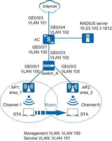
As shown in Figure 1, a department in a campus network deploys two APs that are managed and controlled by an AC. The AC dynamically assigns IP addresses to the APs and STAs. All users in the department belong to the same VLAN, that is, AP1 and AP2 use the same service VLAN. The security policy WPA2-802.1X is used. User data is forwarded through tunnels.
The department requires that services should not be interrupted when a STA moves from AP1 to AP2.
Configuration Roadmap
- The security policy WPA2+802.1X+AES is used and access authentication is required, which results in longer roaming switchover time. Configure fast roaming between APs in the same service VLAN to ensure nonstop service transmission during roaming.
- Configure parameters used for communication between the AC and APs to transmit CAPWAP packets.
- Configure the AC to function as a DHCP server to assign IP addresses to the STAs and APs.
- Configure basic WLAN services to enable the STAs to connect to the WLAN.
Item |
Data |
|---|---|
DHCP server |
The AC functions as a DHCP server to assign IP addresses to the STAs and APs. |
IP address pool for the APs |
10.23.100.2-10.23.100.254/24 |
IP address pool for the STAs |
10.23.101.2-10.23.101.254/24 |
AC's source interface address |
VLANIF100: 10.23.100.1/24 |
RADIUS authentication parameters |
|
User name and password of STAs |
|
802.1X access profile |
|
Authentication profile |
|
AP group |
|
Regulatory domain profile |
|
SSID profile |
|
Security profile |
|
VAP profile |
|
Configuration Notes
- No ACK mechanism is provided for multicast packet transmission on air interfaces. In addition, wireless links are unstable. To ensure stable transmission of multicast packets, they are usually sent at low rates. If a large number of such multicast packets are sent from the network side, the air interfaces may be congested. You are advised to configure multicast packet suppression to reduce impact of a large number of low-rate multicast packets on the wireless network. Exercise caution when configuring the rate limit; otherwise, the multicast services may be affected.
- In direct forwarding mode, you are advised to configure multicast packet suppression on switch interfaces connected to APs.
- In tunnel forwarding mode, you are advised to configure multicast packet suppression in traffic profiles of the AC.
Configure port isolation on the interfaces of the device directly connected to APs. If port isolation is not configured and direct forwarding is used, a large number of unnecessary broadcast packets may be generated in the VLAN, blocking the network and degrading user experience.
In tunnel forwarding mode, the management VLAN and service VLAN cannot be the same. Only packets from the management VLAN are transmitted between the AC and APs. Packets from the service VLAN are not allowed between the AC and APs.
Procedure
- Set the NAC mode to unified on the AC so that users can connect to the network properly.
<HUAWEI> system-view
[HUAWEI] authentication unified-mode

If the NAC mode is changed from traditional to unified, the unified mode takes effect after you save the configuration and restart the device.
- Configure the AC and Switch_A so that the APs and AC can transmit CAPWAP packets.
# Configure Switch_A: add interfaces GE0/0/1, GE0/0/2, and GE0/0/3 to management VLAN 100.
<HUAWEI> system-view
[HUAWEI] sysname Switch_A
[Switch_A] vlan batch 100
[Switch_A] interface gigabitethernet 0/0/1
[Switch_A-GigabitEthernet0/0/1] port link-type trunk
[Switch_A-GigabitEthernet0/0/1] port trunk pvid vlan 100
[Switch_A-GigabitEthernet0/0/1] port trunk allow-pass vlan 100
[Switch_A-GigabitEthernet0/0/1] port-isolate enable
[Switch_A-GigabitEthernet0/0/1] quit
[Switch_A] interface gigabitethernet 0/0/2
[Switch_A-GigabitEthernet0/0/2] port link-type trunk
[Switch_A-GigabitEthernet0/0/2] port trunk pvid vlan 100
[Switch_A-GigabitEthernet0/0/2] port trunk allow-pass vlan 100
[Switch_A-GigabitEthernet0/0/2] port-isolate enable
[Switch_A-GigabitEthernet0/0/2] quit
[Switch_A] interface gigabitethernet 0/0/3
[Switch_A-GigabitEthernet0/0/3] port link-type trunk
[Switch_A-GigabitEthernet0/0/3] port trunk allow-pass vlan 100
[Switch_A-GigabitEthernet0/0/3] quit
# Add GE0/0/1 that connects the AC to Switch_A to VLAN 100.
<HUAWEI> system-view
[HUAWEI] sysname AC
[AC] vlan batch 100
[AC] interface gigabitethernet 0/0/1
[AC-GigabitEthernet0/0/1] port link-type trunk
[AC-GigabitEthernet0/0/1] port trunk allow-pass vlan 100
[AC-GigabitEthernet0/0/1] quit
- Configure the AC to communicate with the upstream device.
# Add AC uplink interface GE0/0/3 to VLAN 101 and add GE0/0/4 of the AC connecting to the RADIUS server to VLAN 102.
[AC] vlan batch 101 102
[AC] interface gigabitethernet 0/0/3
[AC-GigabitEthernet0/0/3] port link-type trunk
[AC-GigabitEthernet0/0/3] port trunk allow-pass vlan 101
[AC-GigabitEthernet0/0/3] quit
[AC] interface gigabitethernet 0/0/4
[AC-GigabitEthernet0/0/4] port link-type trunk
[AC-GigabitEthernet0/0/4] port trunk pvid vlan 102
[AC-GigabitEthernet0/0/4] port trunk allow-pass vlan 102
[AC-GigabitEthernet0/0/4] quit
- Configure the AC as a DHCP server to allocate IP addresses to STAs and APs, and configure VLANIF 102 to allow the AC to communicate with the RADIUS server.
# Configure a DHCP server to assign IP addresses to the APs from the IP address pool on VLANIF 100 and assign IP addresses to STAs from the IP address pool on VLANIF 101.
Configure the DNS server as required. The common methods are as follows:- In interface address pool scenarios, run the dhcp server dns-list ip-address &<1-8> command in the VLANIF interface view.
- In global address pool scenarios, run the dns-list ip-address &<1-8> command in the IP address pool view.
[AC] dhcp enable
[AC] interface vlanif 100
[AC-Vlanif100] ip address 10.23.100.1 24
[AC-Vlanif100] dhcp select interface
[AC-Vlanif100] quit
[AC] interface vlanif 101
[AC-Vlanif101] ip address 10.23.101.1 24
[AC-Vlanif101] dhcp select interface
[AC-Vlanif101] quit
# Configure VLANIF 102.
[AC] interface vlanif 102
[AC-Vlanif102] ip address 10.23.103.2 24
[AC-Vlanif102] quit
- Configure the APs to go online.
# Create an AP group and add the APs to the AP group.
[AC] wlan
[AC-wlan-view] ap-group name ap-group1
[AC-wlan-ap-group-ap-group1] quit
# Create a regulatory domain profile, configure the AC country code in the profile, and apply the profile to the AP group.
[AC-wlan-view] regulatory-domain-profile name domain1
[AC-wlan-regulate-domain-domain1] country-code cn
[AC-wlan-regulate-domain-domain1] quit
[AC-wlan-view] ap-group name ap-group1
[AC-wlan-ap-group-ap-group1] regulatory-domain-profile domain1
Warning: Modifying the country code will clear channel, power and antenna gain configurations of the radio and reset the AP. Continue?[Y/N]:y
[AC-wlan-ap-group-ap-group1] quit
[AC-wlan-view] quit
# Configure the AC's source interface.
[AC] capwap source interface vlanif 100
# Import the APs offline on the AC and add the APs to AP group ap-group1. Assume that the APs' MAC addresses are 60de-4476-e360 and 60de-4474-9640. Configure names for the APs based on the APs' deployment locations, so that you can know where the APs are deployed from their names. For example, name the AP area_1 if it is deployed in Area 1. The default AP authentication mode is MAC address authentication. If the default settings are retained, you do not need to run the ap auth-mode mac-auth command.
In this example, the AP5030DN is used and has two radios: radio 0 (2.4 GHz radio) and radio 1 (5 GHz radio).
[AC] wlan
[AC-wlan-view] ap auth-mode mac-auth
[AC-wlan-view] ap-id 0 ap-mac 60de-4476-e360
[AC-wlan-ap-0] ap-name area_1
Warning: This operation may cause AP reset. Continue? [Y/N]:y
[AC-wlan-ap-0] ap-group ap-group1
Warning: This operation may cause AP reset. If the country code changes, it will clear channel, power and antenna gain configuration s of the radio, Whether to continue? [Y/N]:y
[AC-wlan-ap-0] quit
[AC-wlan-view] ap-id 1 ap-mac 60de-4474-9640
[AC-wlan-ap-1] ap-name area_2
Warning: This operation may cause AP reset. Continue? [Y/N]:y
[AC-wlan-ap-1] ap-group ap-group1
Warning: This operation may cause AP reset. If the country code changes, it will clear channel, power and antenna gain configuration s of the radio, Whether to continue? [Y/N]:y
[AC-wlan-ap-1] quit
# After the APs are powered on, run the display ap all command to check the AP state. If the State field is displayed as nor, the APs have gone online.
[AC-wlan-view] display ap all
Total AP information:
nor  : normal          [2]
Extrainfo : Extra information
P  : insufficient power supply
--------------------------------------------------------------------------------------------------
ID   MAC            Name   Group     IP            Type            State STA Uptime      ExtraInfo
--------------------------------------------------------------------------------------------------
0    60de-4476-e360 area_1 ap-group1 10.23.100.254 AP5030DN        nor   0   5M:2S       -
1    60de-4474-9640 area_2 ap-group1 10.23.100.253 AP5030DN        nor   0   5M:4S       -
--------------------------------------------------------------------------------------------------
Total: 2
- Configure RADIUS authentication parameters.
Configure the same shared key for the AC and RADIUS server.
# Create a RADIUS server template.
[AC] radius-server template radius_huawei
[AC-radius-radius_huawei] radius-server authentication 10.23.103.1 1812
[AC-radius-radius_huawei] radius-server shared-key cipher huawei@123
[AC-radius-radius_huawei] quit
# Configure a RADIUS authentication scheme.
[AC] aaa
[AC-aaa] authentication-scheme radius_huawei
[AC-aaa-authen-radius_huawei] authentication-mode radius
[AC-aaa-authen-radius_huawei] quit
# Create an AAA domain and configure the RADIUS server template and authentication scheme.
[AC-aaa] domain huawei.com
[AC-aaa-domain-huawei.com] radius-server radius_huawei
[AC-aaa-domain-huawei.com] authentication-scheme radius_huawei
[AC-aaa-domain-huawei.com] quit
[AC-aaa] quit
If the domain name huawei.com is configured, you need to add the domain name when entering the user name.
# Test whether a STA can be authenticated using RADIUS authentication. A user name test@huawei.com and password 123456 have been configured on the RADIUS server.
[AC] test-aaa test@huawei.com 123456 radius-template radius_huawei
Info: Account test succeed.
- Configure an 802.1X access profile to manage 802.1X access control parameters.
# Create the 802.1X access profile wlan-dot1x.
[AC] dot1x-access-profile name wlan-dot1x
# Set the authentication mode to EAP relay.
[AC-dot1x-access-profile-wlan-dot1x] dot1x authentication-method eap
[AC-dot1x-access-profile-wlan-dot1x] quit
- Configure an authentication profile named wlan-authentication, apply the 802.1X access profile, and configure a forcible authentication domain.
[AC] authentication-profile name wlan-authentication
[AC-authen-profile-wlan-authentication] dot1x-access-profile wlan-dot1x
[AC-authen-profile-wlan-authentication] access-domain huawei.com dot1x force
[AC-authen-profile-wlan-authentication] quit
- Configure WLAN service parameters.
# Create security profile wlan-security and set the security policy in the profile.
[AC-wlan-view] security-profile name wlan-security
[AC-wlan-sec-prof-wlan-security] security wpa2 dot1x aes
[AC-wlan-sec-prof-wlan-security] quit
# Create SSID profile wlan-ssid and set the SSID name to wlan-net.
[AC-wlan-view] ssid-profile name wlan-ssid
[AC-wlan-ssid-prof-wlan-ssid] ssid wlan-net
[AC-wlan-ssid-prof-wlan-ssid] quit
# Create VAP profile wlan-vap, set the data forwarding mode and service VLANs, and apply the security profile and SSID profile to the VAP profile.
[AC-wlan-view] vap-profile name wlan-vap
[AC-wlan-vap-prof-wlan-vap] forward-mode tunnel
Warning: This action may cause service interruption. Continue?[Y/N]y
[AC-wlan-vap-prof-wlan-vap] service-vlan vlan-id 101
[AC-wlan-vap-prof-wlan-vap] security-profile wlan-security
[AC-wlan-vap-prof-wlan-vap] authentication-profile wlan-authentication
[AC-wlan-vap-prof-wlan-vap] ssid-profile wlan-ssid
[AC-wlan-vap-prof-wlan-vap] quit
# Bind VAP profile wlan-vap to the AP group and apply the profile to radio 0 and radio 1 of the APs.
[AC-wlan-view] ap-group name ap-group1
[AC-wlan-ap-group-ap-group1] vap-profile wlan-vap wlan 1 radio 0
[AC-wlan-ap-group-ap-group1] vap-profile wlan-vap wlan 1 radio 1
[AC-wlan-ap-group-ap-group1] quit
- Set channels and power for the AP radios.
Automatic channel and power calibration functions are enabled by default. The manual channel and power configurations take effect only when these two functions are disabled. The channel and power configuration for the AP radios in this example is for reference only. In actual scenarios, configure channels and power for AP radios based on country codes of APs and network planning results.
# Disable automatic channel and power calibration functions of radio 0, and configure the channel and power for radio 0.[AC-wlan-view] ap-id 0 [AC-wlan-ap-0] radio 0 [AC-wlan-radio-0/0] calibrate auto-channel-select disable [AC-wlan-radio-0/0] calibrate auto-txpower-select disable [AC-wlan-radio-0/0] channel 20mhz 6 Warning: This action may cause service interruption. Continue?[Y/N]y [AC-wlan-radio-0/0] eirp 127 [AC-wlan-radio-0/0] quit# Disable automatic channel and power calibration functions of radio 1, and configure the channel and power for radio 1.[AC-wlan-ap-0] radio 1 [AC-wlan-radio-0/1] calibrate auto-channel-select disable [AC-wlan-radio-0/1] calibrate auto-txpower-select disable [AC-wlan-radio-0/1] channel 20mhz 149 Warning: This action may cause service interruption. Continue?[Y/N]y [AC-wlan-radio-0/1] eirp 127 [AC-wlan-radio-0/1] quit [AC-wlan-ap-0] quit - Verify the configuration.After the configuration is complete, the STA can discover the WLAN with the SSID wlan-net in the coverage area of AP1. Use 802.1X authentication on the STA and enter the user name and password. If the authentication succeeds, the STA can connect to the Internet. Configure the STA according to the configured authentication mode PEAP.
Configuration on the Windows XP operating system:
- On the Association tab page of the Wireless network properties dialog box, add SSID wlan-net, set the authentication mode to WPA2, encryption mode to CCMP, and encryption algorithm to AES.
- On the Authentication tab page, set EAP type to PEAP and click Properties. In the Protected EAP Properties dialog box, deselect Validate server certificate and click Configure. In the displayed dialog box, deselect Automatically use my Windows logon name and password and click OK.
Configuration on the Windows 7 operating system:
- Access the Manage wireless networks page, click Add, and select Manually create a network profile. Add SSID wlan-net. Set the authentication mode to WPA2-Enterprise, and encryption algorithm to AES. Click Next.
- Click Change connection settings. On the Wireless Network Properties page that is displayed, select the Security tab page and click Settings. On the Protected EAP Properties page, deselect Validate server certificate and click Configure. On the dialog box that is displayed, deselect Automatically use my Windows logon name and password and click OK.
- On the Wireless Network Properties page, click Advanced settings. On the Advanced settings page that is displayed, select Specify authentication mode, set the identity authentication mode to User authentication, and click OK.
In the coverage area of AP1, connect the STA to the wireless network with SSID wlan-net and enter the password 123456. After the STA successfully associates with the network, run the display station ssid wlan-net command on the AC. The command output shows that the STA with MAC address e019-1dc7-1e08 has associated with AP1.[AC-wlan-view] display station ssid wlan-net Rf/WLAN: Radio ID/WLAN ID Rx/Tx: link receive rate/link transmit rate(Mbps) --------------------------------------------------------------------------------- STA MAC AP ID Ap name Rf/WLAN Band Type Rx/Tx RSSI VLAN IP address --------------------------------------------------------------------------------- e019-1dc7-1e08 0 area_1 1/1 5G 11n 38/64 -68 101 10.23.101.254 --------------------------------------------------------------------------------- Total: 1 2.4G: 0 5G: 1
When the STA moves from the coverage of AP1 to AP2, run the display station ssid wlan-net command on the AC to check the STA access information. The STA is associated with AP2.[AC-wlan-view] display station ssid wlan-net Rf/WLAN: Radio ID/WLAN ID Rx/Tx: link receive rate/link transmit rate(Mbps) ---------------------------------------------------------------------------------------- STA MAC AP ID Ap name Rf/WLAN Band Type Rx/Tx RSSI VLAN IP address ---------------------------------------------------------------------------------------- e019-1dc7-1e08 1 area_2 1/1 5G 11n 46/59 -58 101 10.23.101.254 ---------------------------------------------------------------------------------------- Total: 1 2.4G: 0 5G: 1
Run the display station roam-track sta-mac e019-1dc7-1e08 command on the AC to check the STA roaming track.[AC-wlan-view] display station roam-track sta-mac e019-1dc7-1e08 Access SSID:huawei Rx/Tx:link receive rate/link transmit rate(Mbps) c:PMK Cache Roam r:802.11r Roam s:Same Frequency Network ------------------------------------------------------------------------------ L2/L3 AC IP AP name Radio ID BSSID TIME In/Out RSSI Out Rx/Tx ------------------------------------------------------------------------------ -- 10.23.100.1 area_1 0 60de-4476-e360 2015/02/07 17:48:30 -51/-48 46/13 L2 10.23.100.1 area_2 0 60de-4474-9640 2015/02/07 17:54:50 -58/- -/- ------------------------------------------------------------------------------ Number: 1
Configuration Files
Switch_A configuration file
#
sysname Switch_A
#
vlan batch 100
#
interface GigabitEthernet0/0/1
 port link-type trunk
 port trunk pvid vlan 100
 port trunk allow-pass vlan 100
 port-isolate enable group 1
#
interface GigabitEthernet0/0/2
 port link-type trunk
 port trunk pvid vlan 100
 port trunk allow-pass vlan 100
 port-isolate enable group 1
#
interface GigabitEthernet0/0/3
 port link-type trunk
 port trunk allow-pass vlan 100
#
return
AC configuration file
#
sysname AC
#
vlan batch 100 to 102
#
authentication-profile name wlan-authentication
 dot1x-access-profile wlan-dot1x
 authentication-scheme radius_huawei
 radius-server radius_huawei
#
dot1x-access-profile name wlan-dot1x
#
dhcp enable
#
radius-server template radius_huawei
 radius-server shared-key cipher %^%#*7d1;XNof/|Q0:DsP!,W51DIYPx}`AARBdJ'0B^$%^%#
 radius-server authentication 10.23.103.1 1812 weight 80
#
aaa
 authentication-scheme radius_huawei
  authentication-mode radius
#
interface Vlanif100
 ip address 10.23.100.1 255.255.255.0
 dhcp select interface
#
interface Vlanif101
 ip address 10.23.101.1 255.255.255.0
 dhcp select interface
#
interface Vlanif102
 ip address 10.23.103.2 255.255.255.0
#
interface GigabitEthernet0/0/1
 port link-type trunk
 port trunk allow-pass vlan 100
#
interface GigabitEthernet0/0/3
 port link-type trunk
 port trunk allow-pass vlan 101
#
interface GigabitEthernet0/0/4
 port link-type trunk
 port trunk pvid vlan 102
 port trunk allow-pass vlan 102
#
capwap source interface vlanif100
#
wlan
 security-profile name wlan-security
  security wpa2 dot1x aes
 ssid-profile name wlan-ssid
  ssid wlan-net
 vap-profile name wlan-vap
  forward-mode tunnel
  service-vlan vlan-id 101
  ssid-profile wlan-ssid
  security-profile wlan-security
  authentication-profile wlan-authentication
 regulatory-domain-profile name domain1
 ap-group name ap-group1
  regulatory-domain-profile domain1
  radio 0
   vap-profile wlan-vap wlan 1
  radio 1
   vap-profile wlan-vap wlan 1
 ap-id 0 type-id 35 ap-mac 60de-4476-e360 ap-sn 210235554710CB000042
  ap-name area_1
  ap-group ap-group1
  radio 0
   channel 20mhz 6
   eirp 127
   calibrate auto-channel-select disable
   calibrate auto-txpower-select disable
  radio 1
   channel 20mhz 149
   eirp 127
   calibrate auto-channel-select disable
   calibrate auto-txpower-select disable
 ap-id 1 type-id 35 ap-mac 60de-4474-9640 ap-sn 210235419610D2000097
  ap-name area_2
  ap-group ap-group1
#
return