Example for Configuring WIDS and WIPS
Configuration Process
You need to configure and maintain WLAN features and functions in different profiles. These WLAN profiles include regulatory domain profile, radio profile, VAP profile, AP system profile, AP wired port profile, WIDS profile, WDS profile, and Mesh profile. When configuring WLAN services, you need to set related parameters in the WLAN profiles and bind the profiles to the AP group or APs. Then the configuration is automatically delivered to and takes effect on the APs. WLAN profiles can reference one another; therefore, you need to know the relationships among the profiles before configuring them. For details about the profile relationships and their basic configuration procedure, see WLAN Service Configuration Procedure.
Networking Requirements
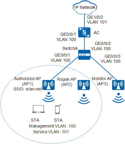
As shown in Figure 1, an enterprise branch deploys WLAN basic services and provides a WLAN with the SSID of wlan-net for employees to access enterprise network resources. STAs automatically obtain IP addresses.
The branch locates in an open place, making the WLAN vulnerable to attacks. A rogue AP (AP2) having the same SSID wlan-net is deployed on the WLAN and attempts to steal enterprise business information by establishing connections with STAs. This rogue AP threatens information security on the enterprise network. To prevent such attack, deploy a monitor AP (AP3) and configure WIDS and WIPS functions to enable the AC to detect AP2 (neither managed by the local AC nor in the authorized AP list), preventing STAs from associating with AP2.
Configuration Roadmap
- Configure basic WLAN services to enable STAs to connect to the WLAN.
- Configure AP3 to work in monitor mode so that AP3 can detect and report information about wireless devices to the AC.
- Configure WIDS and WIPS so that the AC can contain the detected rogue APs (AP2 in this example) and disconnect STAs from AP2.

The following example configures WIDS and WIPS on the 2.4G radio of AP3. The configuration on the 5G radio is similar.
Item |
Data |
|---|---|
| DHCP server | The AC functions as a DHCP server to assign IP addresses to the STAs and AP. |
| IP address pool for the AP | 10.23.100.2-10.23.100.254/24 |
| IP address pool for STAs | 10.23.101.2-10.23.101.254/24 |
| AC's source interface address | VLANIF 100: 10.23.100.1/24 |
| AP group |
|
|
|
| Regulatory domain profile |
|
| SSID profile |
|
| Security profile |
|
| VAP profile |
|
|
|
| WIDS profile |
|
Configuration Notes
- No ACK mechanism is provided for multicast packet transmission on air interfaces. In addition, wireless links are unstable. To ensure stable transmission of multicast packets, they are usually sent at low rates. If a large number of such multicast packets are sent from the network side, the air interfaces may be congested. You are advised to configure multicast packet suppression to reduce impact of a large number of low-rate multicast packets on the wireless network. Exercise caution when configuring the rate limit; otherwise, the multicast services may be affected.
- In direct forwarding mode, you are advised to configure multicast packet suppression on switch interfaces connected to APs.
- In tunnel forwarding mode, you are advised to configure multicast packet suppression in traffic profiles of the AC.
Configure port isolation on the interfaces of the device directly connected to APs. If port isolation is not configured and direct forwarding is used, a large number of unnecessary broadcast packets may be generated in the VLAN, blocking the network and degrading user experience.
In tunnel forwarding mode, the management VLAN and service VLAN cannot be the same. Only packets from the management VLAN are transmitted between the AC and APs. Packets from the service VLAN are not allowed between the AC and APs.
Procedure
- Set the NAC mode to unified on the AC so that users can connect to the network properly.
<HUAWEI> system-view
[HUAWEI] authentication unified-mode
If the NAC mode is changed from traditional to unified, the unified mode takes effect after you save the configuration and restart the device.
- Configure the SwitchA and AC so that the AP and AC can transmit CAPWAP packets.
# Add GE0/0/1 and GE0/0/3 that connects SwitchA to the AP to management VLAN 100 and add GE0/0/2 that connects SwitchA to the AC to the same VLAN.
<HUAWEI> system-view
[HUAWEI] sysname SwitchA
[SwitchA] vlan batch 100
[SwitchA] interface gigabitethernet 0/0/1
[SwitchA-GigabitEthernet0/0/1] port link-type trunk
[SwitchA-GigabitEthernet0/0/1] port trunk pvid vlan 100
[SwitchA-GigabitEthernet0/0/1] port trunk allow-pass vlan 100
[SwitchA-GigabitEthernet0/0/1] quit
[SwitchA] interface gigabitethernet 0/0/2
[SwitchA-GigabitEthernet0/0/2] port link-type trunk
[SwitchA-GigabitEthernet0/0/2] port trunk allow-pass vlan 100
[SwitchA-GigabitEthernet0/0/2] quit
[SwitchA] interface gigabitethernet 0/0/3
[SwitchA-GigabitEthernet0/0/3] port link-type trunk
[SwitchA-GigabitEthernet0/0/3] port trunk pvid vlan 100
[SwitchA-GigabitEthernet0/0/3] port trunk allow-pass vlan 100
[SwitchA-GigabitEthernet0/0/3] quit
# Add GE0/0/1 that connects the AC to SwitchA to VLAN 100.
[HUAWEI] sysname AC
[AC] vlan batch 100 101
[AC] interface gigabitethernet 0/0/1
[AC-GigabitEthernet0/0/1] port link-type trunk
[AC-GigabitEthernet0/0/1] port trunk allow-pass vlan 100
[AC-GigabitEthernet0/0/1] quit
- Configure the AC to communicate with the upstream device.
Configure AC uplink interfaces to transparently transmit packets of service VLANs as required and communicate with the upstream device.
# Add AC uplink interface GE0/0/2 to service VLAN 101.
[AC] interface gigabitethernet 0/0/2
[AC-GigabitEthernet0/0/2] port link-type trunk
[AC-GigabitEthernet0/0/2] port trunk allow-pass vlan 101
[AC-GigabitEthernet0/0/2] quit
- Configure the AC as a DHCP server to allocate IP addresses to STAs and the AP.
# Configure the AC as the DHCP server to allocate an IP address to the AP from the IP address pool on VLANIF 100, and allocate IP addresses to STAs from the IP address pool on VLANIF 101.
Configure the DNS server as required. The common methods are as follows:- In interface address pool scenarios, run the dhcp server dns-list ip-address &<1-8> command in the VLANIF interface view.
- In global address pool scenarios, run the dns-list ip-address &<1-8> command in the IP address pool view.
[AC] dhcp enable
[AC] interface vlanif 100
[AC-Vlanif100] ip address 10.23.100.1 24
[AC-Vlanif100] dhcp select interface
[AC-Vlanif100] quit
[AC] interface vlanif 101
[AC-Vlanif101] ip address 10.23.101.1 24
[AC-Vlanif101] dhcp select interface
[AC-Vlanif101] quit
- Configure the AP to go online.
# Create AP groups ap-group1 and ap-group2.
[AC] wlan
[AC-wlan-view] ap-group name ap-group1
[AC-wlan-ap-group-ap-group1] quit
[AC-wlan-view] ap-group name ap-group2
[AC-wlan-ap-group-ap-group2] quit
# Create a regulatory domain profile, configure the AC country code in the profile, and apply the profile to the AP group.
[AC-wlan-view] regulatory-domain-profile name domain1
[AC-wlan-regulate-domain-domain1] country-code cn
[AC-wlan-regulate-domain-domain1] quit
[AC-wlan-view] ap-group name ap-group1
[AC-wlan-ap-group-ap-group1] regulatory-domain-profile domain1
Warning: Modifying the country code will clear channel, power and antenna gain configurations of the radio and reset the AP. Continue?[Y/N]:y  [AC-wlan-ap-group-ap-group1] quit
[AC-wlan-view] ap-group name ap-group2
[AC-wlan-ap-group-ap-group2] regulatory-domain-profile domain1
Warning: Modifying the country code will clear channel, power and antenna gain configurations of the radio and reset the AP. Continue?[Y/N]:y  [AC-wlan-ap-group-ap-group2] quit
[AC-wlan-view] quit
# Configure the AC's source interface.
[AC] capwap source interface vlanif 100
# Import the AP offline on the AC and add the AP1 and AP3 to ap-group1 and ap-group2. Assume that the AP1's MAC address is 60de-4476-e360 and the AP3's MAC address is dcd2-fc04-b500.. The default AP authentication mode is MAC address authentication. If the default settings are retained, you do not need to run the ap auth-mode mac-auth command.
In this example, the AP5030DN is used and has two radios: radio 0 (2.4 GHz radio) and radio 1 (5 GHz radio).
[AC] wlan
[AC-wlan-view] ap auth-mode mac-auth
[AC-wlan-view] ap-id 0 ap-mac 60de-4476-e360
[AC-wlan-ap-0] ap-name AP1
[AC-wlan-ap-0] ap-group ap-group1
Warning: This operation may cause AP reset. If the country code changes, it will clear channel, power and antenna gain configuration s of the radio, Whether to continue? [Y/N]:y  [AC-wlan-ap-0] quit
[AC-wlan-view] ap-id 1 ap-mac dcd2-fc04-b500
[AC-wlan-ap-1] ap-name AP3
[AC-wlan-ap-1] ap-group ap-group2
Warning: This operation may cause AP reset. If the country code changes, it will clear channel, power and antenna gain configuration s of the radio, Whether to continue? [Y/N]:y  [AC-wlan-ap-1] quit
# After the AP is powered on, run the display ap all command to check the AP state. If the State field is displayed as nor, the AP goes online normally.
[AC-wlan-view] display ap all Total AP information: nor : normal [2] -------------------------------------------------------------------------------- ID MAC Name Group IP Type State STA Uptime -------------------------------------------------------------------------------- 0 60de-4476-e360 AP1 ap-group1 10.23.100.253 AP5030DN nor 0 10S 1 dcd2-fc04-b500 AP3 ap-group2 10.23.100.254 AP5030DN nor 0 15S -------------------------------------------------------------------------------- Total: 2 - Configure WLAN service parameters.
# Create the security profile wlan-security and set the security policy in the profile.
[AC-wlan-view] security-profile name wlan-security
[AC-wlan-sec-prof-wlan-security] security wpa2 psk pass-phrase a1234567 aes
[AC-wlan-sec-prof-wlan-security] quit
# Create the SSID profile wlan-ssid and set the SSID name to wlan-net.
[AC-wlan-view] ssid-profile name wlan-ssid
[AC-wlan-ssid-prof-wlan-ssid] ssid wlan-net
[AC-wlan-ssid-prof-wlan-ssid] quit
# Create the VAP profile wlan-vap1, set the data forwarding mode and service VLAN, and apply the security profile and SSID profile to the VAP profile.
[AC-wlan-view] vap-profile name wlan-vap1
[AC-wlan-vap-prof-wlan-vap1] forward-mode tunnel
[AC-wlan-vap-prof-wlan-vap1] service-vlan vlan-id 101
[AC-wlan-vap-prof-wlan-vap1] security-profile wlan-security
[AC-wlan-vap-prof-wlan-vap1] ssid-profile wlan-ssid
[AC-wlan-vap-prof-wlan-vap1] quit
# Create the VAP profile wlan-vap2, and apply the SSID profile to the VAP profile.
[AC-wlan-view] vap-profile name wlan-vap2
[AC-wlan-vap-prof-wlan-vap2] ssid-profile wlan-ssid
[AC-wlan-vap-prof-wlan-vap2] quit
# Bind the VAP profile wlan-vap1 to the AP group ap-group1.
[AC-wlan-view] ap-group name ap-group1
[AC-wlan-ap-group-ap-group1] vap-profile wlan-vap1 wlan 1 radio 0
[AC-wlan-ap-group-ap-group1] vap-profile wlan-vap1 wlan 1 radio 1
[AC-wlan-ap-group-ap-group1] quit
# Bind the VAP profile wlan-vap2 to the AP group ap-group2.
[AC-wlan-view] ap-group name ap-group2
[AC-wlan-ap-group-ap-group2] vap-profile wlan-vap2 wlan 2 radio 0
[AC-wlan-ap-group-ap-group2] vap-profile wlan-vap2 wlan 2 radio 1
- Configure radio 0 of AP3 to work in monitor mode.
[AC-wlan-ap-group-ap-group2] radio 0
[AC-wlan-group-radio-ap-group2/0] work-mode monitor
Warning: Modify the work mode may cause business interruption, continue?(y/n):y
- Configure WIDS and WIPS.
# Enable device detection and rogue device containment.
[AC-wlan-group-radio-ap-group2/0] wids device detect enable
[AC-wlan-group-radio-ap-group2/0] wids contain enable
[AC-wlan-group-radio-ap-group2/0] quit
[AC-wlan-ap-group-ap-group2] quit
# Create the WIDS profile wlan-wids and set the containment mode to containing rogue APs.
[AC-wlan-view] wids-profile name wlan-wids
[AC-wlan-wids-prof-wlan-wids] contain-mode spoof-ssid-ap
[AC-wlan-wids-prof-wlan-wids] quit
- Bind the WIDS profile wlan-wids to the AP group ap-group2.
[AC-wlan-view] ap-group name ap-group2
[AC-wlan-ap-group-ap-group2] wids-profile wlan-wids
[AC-wlan-ap-group-ap-group2] quit
- Verify the configuration.
Run the display wlan ids contain ap command. The command output shows information about the contained AP2.
[AC-wlan-view] display wlan ids contain ap
#Rf: Number of monitor radios that have contained the device
CH: Channel number
-------------------------------------------------------------------------------
MAC address     CH  Authentication   Last detected time   #Rf   SSID
-------------------------------------------------------------------------------
000b-6b8f-fc6a  11  open             2014-11-20/16:16:57  1    wlan-net
-------------------------------------------------------------------------------
Total: 1, printed: 1
STAs attempt to connect to the network through AP2. Countermeasures are taken on AP2, so traffic between STAs and AP2 is stopped and then STAs connect to AP1.
C:\Documents and Settings\huawei> ping 10.23.101.22

Pinging 10.23.101.22 with 32 bytes of data:

Request timed out.
Request timed out.
Request timed out.
Request timed out.
Reply from 10.23.101.22: bytes=32 time=1433ms TTL=255
Reply from 10.23.101.22: bytes=32 time=40ms TTL=255
Reply from 10.23.101.22: bytes=32 time=11ms TTL=255
Reply from 10.23.101.22: bytes=32 time=46ms TTL=255
Configuration Files
Configuration file of SwitchA
#
sysname SwitchA
#
vlan batch 100
#
interface GigabitEthernet0/0/1
 port link-type trunk
 port trunk pvid vlan 100
 port trunk allow-pass vlan 100
#
interface GigabitEthernet0/0/2
 port link-type trunk
 port trunk allow-pass vlan 100
#
interface GigabitEthernet0/0/3
 port link-type trunk
 port trunk pvid vlan 100
 port trunk allow-pass vlan 100
#
return
Configuration file of the AC
#
 sysname AC
#
vlan batch 100 to 101
#
dhcp enable
#
interface Vlanif100
 ip address 10.23.100.1 255.255.255.0
 dhcp select interface
#
interface Vlanif101
 ip address 10.23.101.1 255.255.255.0
 dhcp select interface
#
interface GigabitEthernet0/0/1
 port link-type trunk
 port trunk allow-pass vlan 100
#
interface GigabitEthernet0/0/2
 port link-type trunk
 port trunk allow-pass vlan 101
#
capwap source interface vlanif100
#
wlan
 security-profile name wlan-security
  security wpa2 psk pass-phrase %^%#m"tz0f>~7.[`^6RWdzwCy16hJj/Mc!,}s`X*B]}A%^%# aes
 ssid-profile name wlan-ssid
  ssid wlan-net
 vap-profile name wlan-vap1
  forward-mode tunnel
  service-vlan vlan-id 101
  ssid-profile wlan-ssid
  security-profile wlan-security
 vap-profile name wlan-vap2
  ssid-profile wlan-ssid
 regulatory-domain-profile name domain1
 wids-profile name wlan-wids
  contain-mode spoof-ssid-ap
 ap-group name ap-group1
  regulatory-domain-profile domain1
  radio 0
   vap-profile wlan-vap1 wlan 1
  radio 1
   vap-profile wlan-vap1 wlan 1
 ap-group name ap-group2
  regulatory-domain-profile domain1
   wids-profile wlan-wids
  radio 0
   vap-profile wlan-vap2 wlan 2
   work-mode monitor
   wids device detect enable
   wids contain enable
  radio 1
   vap-profile wlan-vap2 wlan 2
 ap-id 0 type-id 35 ap-mac 60de-4476-e360 ap-sn 210235554710CB000042
  ap-name AP1
  ap-group ap-group1
 ap-id 1 type-id 35 ap-mac dcd2-fc04-b500 ap-sn 210235419610D2000097
  ap-name AP3
  ap-group ap-group2
#
return