Example for Configuring Spectrum Analysis
Configuration Process
You need to configure and maintain WLAN features and functions in different profiles. These WLAN profiles include regulatory domain profile, radio profile, VAP profile, AP system profile, AP wired port profile, WIDS profile, WDS profile, and Mesh profile. When configuring WLAN services, you need to set related parameters in the WLAN profiles and bind the profiles to the AP group or APs. Then the configuration is automatically delivered to and takes effect on the APs. WLAN profiles can reference one another; therefore, you need to know the relationships among the profiles before configuring them. For details about the profile relationships and their basic configuration procedure, see WLAN Service Configuration Procedure.
Networking Requirements
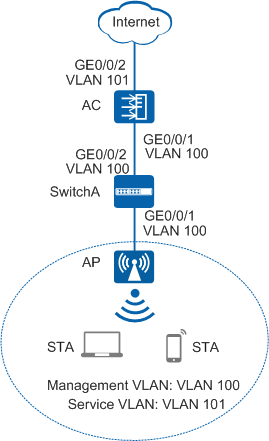
As shown in Figure 1, an enterprise deploys basic WLAN services to enable mobile users to connect to the enterprise network from anywhere at any time. The WLAN SSID is wlan-net, and STAs automatically obtain IP addresses.
The enterprise is located in an open place and the WLAN is therefore easy to be interfered. When discovering severe interference on the WLAN, the network administrator can detect whether non-Wi-Fi interference exists on the WLAN through the spectrum analysis function.
Configuration Roadmap
- Configure the AP, AC, switch, and upper-layer devices to communicate at Layer 2.
- Configure the AC as a DHCP server to assign IP addresses to the APs and STAs.
- Configure the APs to go online.
- Create an AP group and add APs that require the same configuration to the group for unified configuration.
- Configure AC system parameters, including the country code and source interface used by the AC to communicate with the APs.
- Configure the AP authentication mode and import the APs offline to allow the APs to go online.
- Configure WLAN service parameters for STAs to access the WLAN.
- Configure spectrum analysis so that the APs can detect non-Wi-Fi devices and send alarms to the AC.
Item |
Data |
|---|---|
| DHCP server | The AC functions as a DHCP server to assign IP addresses to the APs and STAs. |
| IP address pool for the APs | 10.23.100.2-10.23.100.254/24 |
| IP address pool for the STAs | 10.23.101.2-10.23.101.254/24 |
| IP address of the AC's source interface | VLANIF 100: 10.23.100.1/24 |
| AP group |
|
| Regulatory domain profile |
|
| SSID profile |
|
| Security profile |
|
| VAP profile |
|
| 2G radio profile |
|
| 5G radio profile |
|
| Air scan profile |
|
| Spectrum profile |
|
Configuration Notes
- No ACK mechanism is provided for multicast packet transmission on air interfaces. In addition, wireless links are unstable. To ensure stable transmission of multicast packets, they are usually sent at low rates. If a large number of such multicast packets are sent from the network side, the air interfaces may be congested. You are advised to configure multicast packet suppression to reduce impact of a large number of low-rate multicast packets on the wireless network. Exercise caution when configuring the rate limit; otherwise, the multicast services may be affected.
- In direct forwarding mode, you are advised to configure multicast packet suppression on switch interfaces connected to APs.
- In tunnel forwarding mode, you are advised to configure multicast packet suppression in traffic profiles of the AC.
Configure port isolation on the interfaces of the device directly connected to APs. If port isolation is not configured and direct forwarding is used, a large number of unnecessary broadcast packets may be generated in the VLAN, blocking the network and degrading user experience.
In tunnel forwarding mode, the management VLAN and service VLAN cannot be the same. Only packets from the management VLAN are transmitted between the AC and APs. Packets from the service VLAN are not allowed between the AC and APs.
Procedure
- Set the NAC mode to unified on the AC so that users can connect to the network properly.
<HUAWEI> system-view
[HUAWEI] authentication unified-mode

If the NAC mode is changed from traditional to unified, the unified mode takes effect after you save the configuration and restart the device.
- Configure SwitchA and the AC so that the AP and AC can transmit CAPWAP packets.
# Add GE0/0/1 that connects SwitchA to the AP to management VLAN 100 and add GE0/0/2 that connects SwitchA to the AC to the same VLAN.
<HUAWEI> system-view
[HUAWEI] sysname SwitchA
[SwitchA] vlan batch 100
[SwitchA] interface gigabitethernet 0/0/1
[SwitchA-GigabitEthernet0/0/1] port link-type trunk
[SwitchA-GigabitEthernet0/0/1] port trunk pvid vlan 100
[SwitchA-GigabitEthernet0/0/1] port trunk allow-pass vlan 100
[SwitchA-GigabitEthernet0/0/1] quit
[SwitchA] interface gigabitethernet 0/0/2
[SwitchA-GigabitEthernet0/0/2] port link-type trunk
[SwitchA-GigabitEthernet0/0/2] port trunk allow-pass vlan 100
[SwitchA-GigabitEthernet0/0/2] quit
# Add GE0/0/1 that connects the AC to SwitchA to VLAN 100.
[HUAWEI] sysname AC
[AC] vlan batch 100 101
[AC] interface gigabitethernet 0/0/1
[AC-GigabitEthernet0/0/1] port link-type trunk
[AC-GigabitEthernet0/0/1] port trunk allow-pass vlan 100
[AC-GigabitEthernet0/0/1] quit
- Configure the AC to communicate with the upstream device.
Configure AC uplink interfaces to transparently transmit packets of service VLANs as required and communicate with the upstream device.
# Add AC uplink interface GE0/0/2 to service VLAN 101.
[AC] interface gigabitethernet 0/0/2
[AC-GigabitEthernet0/0/2] port link-type trunk
[AC-GigabitEthernet0/0/2] port trunk allow-pass vlan 101
[AC-GigabitEthernet0/0/2] quit
- Configure the AC as a DHCP server to allocate IP addresses to STAs and the AP.
# Configure the AC as the DHCP server to allocate an IP address to the AP from the IP address pool on VLANIF 100, and allocate IP addresses to STAs from the IP address pool on VLANIF 101.
Configure the DNS server as required. The common methods are as follows:- In interface address pool scenarios, run the dhcp server dns-list ip-address &<1-8> command in the VLANIF interface view.
- In global address pool scenarios, run the dns-list ip-address &<1-8> command in the IP address pool view.
[AC] dhcp enable
[AC] interface vlanif 100
[AC-Vlanif100] ip address 10.23.100.1 24
[AC-Vlanif100] dhcp select interface
[AC-Vlanif100] quit
[AC] interface vlanif 101
[AC-Vlanif101] ip address 10.23.101.1 24
[AC-Vlanif101] dhcp select interface
[AC-Vlanif101] quit
- Configure the AP to go online.
# Create an AP group and add the AP to the AP group.
[AC] wlan
[AC-wlan-view] ap-group name ap-group1
[AC-wlan-ap-group-ap-group1] quit
# Create a regulatory domain profile, configure the AC country code in the profile, and apply the profile to the AP group.
[AC-wlan-view] regulatory-domain-profile name domain1
[AC-wlan-regulate-domain-domain1] country-code cn
[AC-wlan-regulate-domain-domain1] quit
[AC-wlan-view] ap-group name ap-group1
[AC-wlan-ap-group-ap-group1] regulatory-domain-profile domain1
Warning: Modifying the country code will clear channel, power and antenna gain configurations of the radio and reset the AP. Continue?[Y/N]:y
[AC-wlan-ap-group-ap-group1] quit
[AC-wlan-view] quit
# Configure the AC's source interface.
[AC] capwap source interface vlanif 100
# Import the AP offline on the AC and add the AP to AP group ap-group1. Assume that the AP's MAC address is 60de-4476-e360. Configure a name for the AP based on the AP's deployment location, so that you can know where the AP is deployed from its name. For example, name the AP area_1 if it is deployed in Area 1. The default AP authentication mode is MAC address authentication. If the default settings are retained, you do not need to run the ap auth-mode mac-auth command.
In this example, the AP5030DN is used and has two radios: radio 0 (2.4 GHz radio) and radio 1 (5 GHz radio).
[AC] wlan
[AC-wlan-view] ap auth-mode mac-auth
[AC-wlan-view] ap-id 0 ap-mac 60de-4476-e360
[AC-wlan-ap-0] ap-name area_1
Warning: This operation may cause AP reset. Continue? [Y/N]:y
[AC-wlan-ap-0] ap-group ap-group1
Warning: This operation may cause AP reset. If the country code changes, it will clear channel, power and antenna gain configuration s of the radio, Whether to continue? [Y/N]:y
[AC-wlan-ap-0] quit
# After the AP is powered on, run the display ap all command to check the AP state. If the State field is displayed as nor, the AP goes online normally.
[AC-wlan-view] display ap all
Total AP information:
nor  : normal          [1]
Extrainfo : Extra information
P  : insufficient power supply
--------------------------------------------------------------------------------------------------
ID   MAC            Name   Group     IP            Type            State STA Uptime      ExtraInfo
--------------------------------------------------------------------------------------------------
0    60de-4476-e360 area_1 ap-group1 10.23.100.254 AP5030DN        nor   0   10S         -
--------------------------------------------------------------------------------------------------
Total: 1
- Configure WLAN service parameters.# Create security profile wlan-security and set the security policy in the profile.
In this example, the security policy is set to WPA2+PSK+AES and password to a1234567. In actual situations, the security policy must be configured according to service requirements.
[AC-wlan-view] security-profile name wlan-security
[AC-wlan-sec-prof-wlan-security] security wpa2 psk pass-phrase a1234567 aes
[AC-wlan-sec-prof-wlan-security] quit
# Create SSID profile wlan-ssid and set the SSID name to wlan-net.
[AC-wlan-view] ssid-profile name wlan-ssid
[AC-wlan-ssid-prof-wlan-ssid] ssid wlan-net
[AC-wlan-ssid-prof-wlan-ssid] quit
# Create VAP profile wlan-vap, set the data forwarding mode and service VLAN, and apply the security profile and SSID profile to the VAP profile.
[AC-wlan-view] vap-profile name wlan-vap
[AC-wlan-vap-prof-wlan-vap] forward-mode tunnel
[AC-wlan-vap-prof-wlan-vap] service-vlan vlan-id 101
[AC-wlan-vap-prof-wlan-vap] security-profile wlan-security
[AC-wlan-vap-prof-wlan-vap] ssid-profile wlan-ssid
[AC-wlan-vap-prof-wlan-vap] quit
# Bind VAP profile wlan-vap to the AP group and apply the profile to radio 0 and radio 1 of the AP.
[AC-wlan-view] ap-group name ap-group1
[AC-wlan-ap-group-ap-group1] vap-profile wlan-vap wlan 1 radio all
[AC-wlan-ap-group-ap-group1] quit
- Configure spectrum analysis.
[AC-wlan-view] ap-system-profile name spectrum01
[AC-wlan-ap-system-prof-spectrum01] spectrum-analysis server ip-address 10.137.43.4 port 55555 via-ac ac-port 5001
[AC-wlan-ap-system-prof-spectrum01] spectrum-analysis non-wifi-device aging-time 5
[AC-wlan-ap-system-prof-spectrum01] quit
# Create the air scan profile wlan-airscan and configure the scan interval and scan duration.
[AC-wlan-view] air-scan-profile name wlan-airscan
[AC-wlan-air-scan-prof-wlan-airscan] scan-period 80
[AC-wlan-air-scan-prof-wlan-airscan] scan-interval 80000
[AC-wlan-air-scan-prof-wlan-airscan] quit
# Create the 2G radio profile radio2g and bind the air scan profile wlan-airscan to the 2G radio profile.
[AC-wlan-view] radio-2g-profile name radio2g
[AC-wlan-radio-2g-prof-radio2g] air-scan-profile wlan-airscan
[AC-wlan-radio-2g-prof-radio2g] quit
# Create the 5G radio profile radio5g and bind the air scan profile wlan-airscan to the 5G radio profile.
[AC-wlan-view] radio-5g-profile name radio5g
[AC-wlan-radio-5g-prof-radio5g] air-scan-profile wlan-airscan
[AC-wlan-radio-5g-prof-radio5g] quit
# Bind the 5G radio profile radio5g and 2G radio profile radio2g to the AP group ap-group1.
[AC-wlan-view] ap-group name ap-group1
[AC-wlan-ap-group-ap-group1] radio-5g-profile radio5g radio 1
Warning: This action may cause service interruption. Continue?[Y/N]y
[AC-wlan-ap-group-ap-group1] radio-2g-profile radio2g radio 0
Warning: This action may cause service interruption. Continue?[Y/N]y
[AC-wlan-ap-group-ap-group1] quit
# Bind the AP system profile spectrum01 to the AP group ap-group1 and enable spectrum analysis in the AP group.
[AC-wlan-view] ap-group name ap-group1
[AC-wlan-ap-group-ap-group1] ap-system-profile spectrum01
[AC-wlan-ap-group-ap-group1] radio 0
[AC-wlan-group-radio-ap-group1/0] spectrum-analysis enable
[AC-wlan-group-radio-ap-group1/0] quit
[AC-wlan-ap-group-ap-group1] radio 1
[AC-wlan-group-radio-ap-group1/1] spectrum-analysis enable
[AC-wlan-group-radio-ap-group1/1] quit
[AC-wlan-ap-group-ap-group1] quit
- Verify the configuration.
Connect STAs to the WLAN with SSID wlan-net and enter the password a1234567. Run the display station ssid wlan-net command on the AC. The command output shows that the STAs are connected to the WLAN wlan-net.
[AC-wlan-view] display station ssid wlan-net
Rf/WLAN: Radio ID/WLAN ID
Rx/Tx: link receive rate/link transmit rate(Mbps)
---------------------------------------------------------------------------------
STA MAC         AP ID Ap name   Rf/WLAN  Band  Type  Rx/Tx      RSSI  VLAN  IP address
---------------------------------------------------------------------------------
e019-1dc7-1e08  0     area_1    1/1      5G    11n   46/59      -68   101   10.23.101.254
---------------------------------------------------------------------------------
Total: 1 2.4G: 0 5G: 1
Run the display ap-system-profile name spectrum01 command on the AC to check spectrum analysis configuration.
[AC-wlan-view] display ap-system-profile name spectrum01
------------------------------------------------------------------------------
AC priority                   : -
Protect AC IP address         : -
AP management VLAN            : -
Keep service                  : disable
Keep service allow new access : disable
Temporary management switch   : disable
Mesh role                     : mesh-node
STA access mode               : disable
STA whitelist profile         : -
STA blacklist profile         : -
EAPOL start mode              : multicast
EAPOL start transform         : equal-bssid
EAPOL response mode           : unicast learning
EAPOL response transform      : equal-bssid
AP LLDP message transmission delay time(s): 2
AP LLDP message transmission hold multiplier: 4
AP LLDP message transmission interval time(s): 30
AP LLDP restart delay time(s) : 2
AP LLDP admin status          : txrx
AP LLDP report interval time(s): 30
AP high temperature threshold(degree C): -
AP low temperature threshold(degree C): -
AP CPU usage threshold(%)     : 90
AP memory usage threshold(%)  : 80
Alarm restriction             : enable
Alarm restriction period(s)   : 60
Log server IP address         : 0.0.0.0
Log record level              : info
Ethernet port MTU(byte)       : 1500
Telnet                        : disable
STelnet server                : enable
SFTP server                   : enable
Console                       : enable
Antenna output mode           : split
Led                           : on
Sample time(s)                : 30
Dynamic blacklist aging time(s): 600
MPP active reselection         : disable
AP report to                   : AC
Server IP                      : 10.137.43.4
Server port                    : 55555
AC port                        : 5001
Device aging-time(minute)      : 5
PoE max power                  : 380000
PoE power reserved(%)          : 0
PoE power threshold(%)         : 100
PoE af inrush                  : disable
PoE high inrush                : disable
------------------------------------------------------------------------------
Run the display spectrum-analysis server-reporter command on the AC to check the APs that report spectrum packets to the spectrum server.
[AC-wlan-view] display spectrum-analysis server-reporter
------------------------------------------------------------
ID    AP name                          Radio ID
------------------------------------------------------------
1     area_1                           0
1     area_1                           1
------------------------------------------------------------
Total: 2
Run the display wlan non-wifi-device all command on the AC to check the detected non-Wi-Fi devices.
[AC-wlan-view] display wlan non-wifi-device all
----------------------------------------------------------------
Detect AP name                         : huawei
Detect AP radio ID                     : 1
Detect AP channel                      : 36
Non-Wi-Fi device type                  : 9
Non-Wi-Fi device name                  : Unknown fix freq device
Non-Wi-Fi device frequency type        : Narrow bandwidth
Non-Wi-Fi device channel               : 149,150
Non-Wi-Fi device RSSI                  : -62,-66
Non-Wi-Fi device detect time last      : 2015-07-02/08:16:56
Non-Wi-Fi device center frequency(MHz) : 5749
Non-Wi-Fi device bandwidth(KHz)        : 70
Non-Wi-Fi device duty(%)               : 100
Non-Wi-Fi device interfere level       : 3
----------------------------------------------------------------
Total: 1
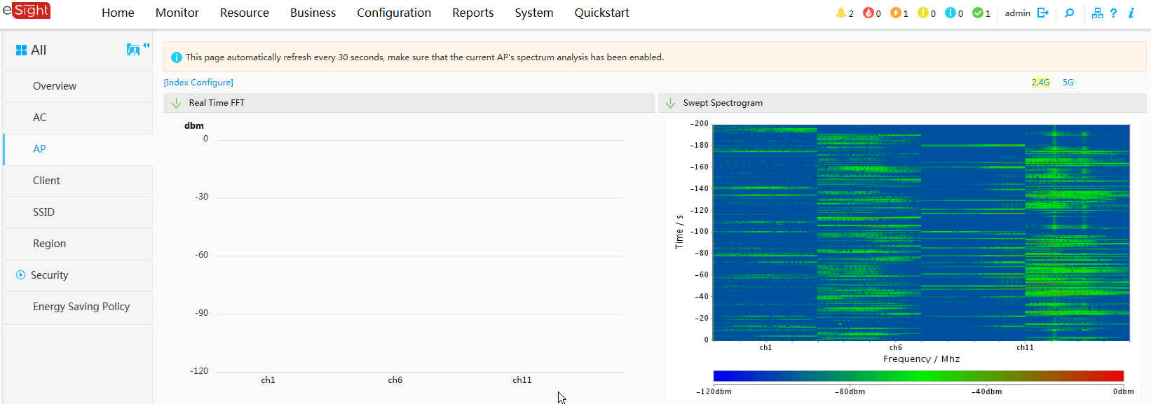
- View AP spectrum on eSight to learn AP channel interference in deployment sites.
- Choose from the main menu.
Use either of the following methods to access the region object manager.
- In the monitoring mode, right-click a region in on the left pane, and select .
- In the 360 topology view, click a region name in the region list at the bottom of page to display the object manager of the selected region.
In the region object manager view, you can click to select other regions.
- Choose from the navigation tree of the Region Object Manager.
- In the AP list, click
 and select in the column.
 - Click , choose a spectrum graph type, and click to view the spectrum graph of the selected AP.
- The spectrum graphs show that the interference is mostly within the range of -80 dBm to -40 dBm and most serious on channel 11.
Configuration Files
- SwitchA configuration file
#
sysname SwitchA
#
vlan batch 100
#
interface GigabitEthernet0/0/1
 port link-type trunk
 port trunk pvid vlan 100
 port trunk allow-pass vlan 100
#
interface GigabitEthernet0/0/2
 port link-type trunk
 port trunk allow-pass vlan 100
#
return
AC configuration file
#
 sysname AC
#
vlan batch 100 to 101
#
dhcp enable
#
interface Vlanif100
 ip address 10.23.100.1 255.255.255.0
 dhcp select interface
#
interface Vlanif101
 ip address 10.23.101.1 255.255.255.0
 dhcp select interface
#
interface GigabitEthernet0/0/1
 port link-type trunk
 port trunk pvid vlan 100
 port trunk allow-pass vlan 100
#
interface GigabitEthernet0/0/2
 port link-type trunk
 port trunk allow-pass vlan 101
#
capwap source interface vlanif100
#
wlan
 security-profile name wlan-security
  security wpa2 psk pass-phrase %^%#m"tz0f>~7.[`^6RWdzwCy16hJj/Mc!,}s`X*B]}A%^%# aes
 ssid-profile name wlan-ssid
  ssid wlan-net
 vap-profile name wlan-vap
  forward-mode tunnel
  service-vlan vlan-id 101
  ssid-profile wlan-ssid
  security-profile wlan-security
 regulatory-domain-profile name domain1
 air-scan-profile name wlan-airscan
  scan-period 80
  scan-interval 80000
 radio-2g-profile name radio2g
  air-scan-profile wlan-airscan
 radio-5g-profile name radio5g
  air-scan-profile wlan-airscan
 ap-system-profile name spectrum01
  spectrum-analysis server ip-address 10.137.43.4 port 55555 via-ac ac-port 5001
  spectrum-analysis non-wifi-device aging-time 5
 ap-group name ap-group1
  ap-system-profile spectrum01
  regulatory-domain-profile domain1
  radio 0
   radio-2g-profile radio2g
   vap-profile wlan-vap wlan 1
   spectrum-analysis enable
  radio 1
   radio-5g-profile radio5g
   vap-profile wlan-vap wlan 1
   spectrum-analysis enable
 ap-id 0 type-id 19 ap-mac 60de-4476-e360 ap-sn 210235554710CB000042
  ap-name area_1
  ap-group ap-group1
#
return