Example for Configuring the WLAN Service Using WDS Technology
Configuration Process
You need to configure and maintain WLAN features and functions in different profiles. These WLAN profiles include regulatory domain profile, radio profile, VAP profile, AP system profile, AP wired port profile, WIDS profile, WDS profile, and Mesh profile. When configuring WLAN services, you need to set related parameters in the WLAN profiles and bind the profiles to the AP group or APs. Then the configuration is automatically delivered to and takes effect on the APs. WLAN profiles can reference one another; therefore, you need to know the relationships among the profiles before configuring them. For details about the profile relationships and their basic configuration procedure, see WLAN Service Configuration Procedure.
Networking Requirements
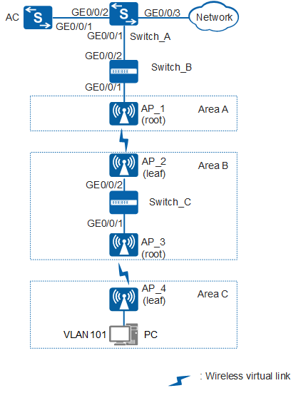
An enterprise has three areas: Area A, Area B, and Area C. In the office environment, AP_1 in Area A can be connected to the AC through a network cable; AP_2 and AP_3 in Area B can be connected through a cable but cannot be connected to the AC in wired mode; Area C is near Area B but AP_4 in Area C cannot be connected to the AC through a network cable either. The enterprise requires that APs be connected to each other in back-to-back WDS mode and go online on the AC to provide network services for PCs in VLAN 101, as shown in Figure 1:
Configuration Roadmap
- Configure WDS links in Area A and Area B so that AP_1 and AP_2 can go online on the AC.
- Configure Switch_C to enable AP_2 and AP_3 to communicate through the wired network.
- Configure WDS links in Area B and Area C so that AP_4 can go online on the AC.

In this example, the access switches Switch_B and Switch_C and aggregation switch Switch_A are Huawei products.
AP |
Type |
MAC |
|---|---|---|
AP_1 |
AP8130DN |
60de-4474-9640 |
AP_2 |
AP8130DN |
dcd2-fc04-b500 |
AP_3 |
AP8130DN |
dcd2-fcf6-76a0 |
AP_4 |
AP8130DN |
60de-4476-e360 |
Item |
Data |
|---|---|
VLAN |
Management VLAN: VLAN 100 |
Service VLAN: VLAN 101 |
|
IP address of the AC's source interface |
VLANIF 100: 10.23.100.1/24 |
WDS profile |
|
WDS role |
|
WDS name |
wds-net |
WDS whitelist |
|
Radio used by WDS |
Radio 1 (AP_1 and AP_2):
Radio 1 (AP_3 and AP_4):
|
Security profile |
|
AP group |
|
Configuration Notes
- No ACK mechanism is provided for multicast packet transmission on air interfaces. In addition, wireless links are unstable. To ensure stable transmission of multicast packets, they are usually sent at low rates. If a large number of such multicast packets are sent from the network side, the air interfaces may be congested. You are advised to configure multicast packet suppression to reduce impact of a large number of low-rate multicast packets on the wireless network. Exercise caution when configuring the rate limit; otherwise, the multicast services may be affected.
- In direct forwarding mode, you are advised to configure multicast packet suppression on switch interfaces connected to APs.
- In tunnel forwarding mode, you are advised to configure multicast packet suppression in traffic profiles of the AC.
Configure port isolation on the interfaces of the device directly connected to APs. If port isolation is not configured and direct forwarding is used, a large number of unnecessary broadcast packets may be generated in the VLAN, blocking the network and degrading user experience.
In tunnel forwarding mode, the management VLAN and service VLAN cannot be the same. Only packets from the management VLAN are transmitted between the AC and APs. Packets from the service VLAN are not allowed between the AC and APs.
Procedure
- Configure the AC to communicate with AP_1 and AP_2 to communicate with AP_3.
# Configure the access switch Switch_B. Add GE0/0/1 of Switch_B to VLAN 100 (management VLAN) and set the PVID of the interface to VLAN 100. Configure GE0/0/1 and GE0/0/2 to allow packets from VLAN 100 and VLAN 101 to pass through.
<HUAWEI> system-view
[HUAWEI] sysname Switch_B
[Switch_B] vlan batch 100 to 101
[Switch_B] interface gigabitEthernet 0/0/1
[Switch_B-GigabitEthernet0/0/1] port link-type trunk
[Switch_B-GigabitEthernet0/0/1] port trunk pvid vlan 100
[Switch_B-GigabitEthernet0/0/1] port trunk allow-pass vlan 100 to 101
[Switch_B-GigabitEthernet0/0/1] port-isolate enable
[Switch_B-GigabitEthernet0/0/1] quit
[Switch_B] interface gigabitEthernet 0/0/2
[Switch_B-GigabitEthernet0/0/2] port link-type trunk
[Switch_B-GigabitEthernet0/0/2] port trunk allow-pass vlan 100 to 101
[Switch_B-GigabitEthernet0/0/2] quit
# Configure the aggregation switch Switch_A. Configure GE0/0/1 to allow packets from VLAN 100 and VLAN 101 to pass through, GE0/0/2 to allow packets from VLAN 100 to pass through, and GE0/0/3 to allow packets from VLAN 101 to pass through.
<HUAWEI> system-view
[HUAWEI] sysname Switch_A
[Switch_A] vlan batch 100 to 101
[Switch_A] interface gigabitEthernet 0/0/1
[Switch_A-GigabitEthernet0/0/1] port link-type trunk
[Switch_A-GigabitEthernet0/0/1] port trunk allow-pass vlan 100 to 101
[Switch_A-GigabitEthernet0/0/1] quit
[Switch_A] interface gigabitEthernet 0/0/2
[Switch_A-GigabitEthernet0/0/2] port link-type trunk
[Switch_A-GigabitEthernet0/0/2] port trunk allow-pass vlan 100
[Switch_A-GigabitEthernet0/0/2] quit
[Switch_A] interface gigabitEthernet 0/0/3
[Switch_A-GigabitEthernet0/0/3] port link-type trunk
[Switch_A-GigabitEthernet0/0/3] port trunk allow-pass vlan 101
[Switch_A-GigabitEthernet0/0/3] quit
# Configure GE0/0/1 of the AC to allow packets from VLAN 100 to pass through.
<HUAWEI> system-view
[HUAWEI] sysname AC
[AC] vlan batch 100 to 101
[AC] interface gigabitEthernet 0/0/1
[AC-GigabitEthernet0/0/1] port link-type trunk
[AC-GigabitEthernet0/0/1] port trunk allow-pass vlan 100
[AC-GigabitEthernet0/0/1] quit
# Configure the access switch Switch_C. Configure GE0/0/1 and GE0/0/2 to allow packets from the service and management VLANs to pass through.
<HUAWEI> system-view
[HUAWEI] sysname Switch_C
[Switch_C] vlan batch 100 to 101
[Switch_C] interface gigabitEthernet 0/0/1
[Switch_C-GigabitEthernet0/0/1] port link-type trunk
[Switch_C-GigabitEthernet0/0/1] port trunk allow-pass vlan 100 to 101
[Switch_C-GigabitEthernet0/0/1] quit
[Switch_C] interface gigabitEthernet 0/0/2
[Switch_C-GigabitEthernet0/0/2] port link-type trunk
[Switch_C-GigabitEthernet0/0/2] port trunk allow-pass vlan 100 to 101
[Switch_C-GigabitEthernet0/0/2] quit
- Configure Switch_A to assign IP addresses to PCs and the AC to assign IP addresses to APs.
# Configure Switch_A as a DHCP server to assign IP addresses to PCs from an interface address pool.
Configure the DNS server as required. The common methods are as follows:- In interface address pool scenarios, run the dhcp server dns-list ip-address &<1-8> command in the VLANIF interface view.
- In global address pool scenarios, run the dns-list ip-address &<1-8> command in the IP address pool view.
[Switch_A] dhcp enable
[Switch_A] interface vlanif 101
[Switch_A-Vlanif101] ip address 10.23.101.1 24
[Switch_A-Vlanif101] dhcp select interface
[Switch_A-Vlanif101] quit
# Enable the DHCP function on the AC to allow it to assign IP addresses to APs from an interface address pool.
[AC] dhcp enable
[AC] interface vlanif 100
[AC-Vlanif100] ip address 10.23.100.1 24
[AC-Vlanif100] dhcp select interface
[AC-Vlanif100] quit
- Configure the AP groups, country code, and AC's source interface.
# Create AP group wds-root1 and AP group wds-root2 for root APs and AP group wds-leaf1 and AP group wds-leaf2 for leaf APs.
[AC] wlan
[AC-wlan-view] ap-group name wds-root1
[AC-wlan-ap-group-wds-root1] quit
[AC-wlan-view] ap-group name wds-root2
[AC-wlan-ap-group-wds-root2] quit
[AC-wlan-view] ap-group name wds-leaf1
[AC-wlan-ap-group-wds-leaf1] quit
[AC-wlan-view] ap-group name wds-leaf2
[AC-wlan-ap-group-wds-leaf2] quit
# Create a regulatory domain profile, configure the AC country code in the profile, and apply the profile to the AP groups.
[AC-wlan-view] regulatory-domain-profile name domain1
[AC-wlan-regulate-domain-domain1] country-code cn
[AC-wlan-regulate-domain-domain1] quit
[AC-wlan-view] ap-group name wds-root1
[AC-wlan-ap-group-wds-root1] regulatory-domain-profile domain1
Warning: Modifying the country code will clear channel, power and antenna gain configurations of the radio and reset the AP. Continue?[Y/N]:y
[AC-wlan-ap-group-wds-root1] quit
[AC-wlan-view] ap-group name wds-root2
[AC-wlan-ap-group-wds-root2] regulatory-domain-profile domain1
Warning: Modifying the country code will clear channel, power and antenna gain configurations of the radio and reset the AP. Continue?[Y/N]:y
[AC-wlan-ap-group-wds-root2] quit
[AC-wlan-view] ap-group name wds-leaf1
[AC-wlan-ap-group-wds-leaf1] regulatory-domain-profile domain1
Warning: Modifying the country code will clear channel, power and antenna gain configurations of the radio and reset the AP. Continue?[Y/N]:y
[AC-wlan-ap-group-wds-leaf1] quit
[AC-wlan-view] ap-group name wds-leaf2
[AC-wlan-ap-group-wds-leaf2] regulatory-domain-profile domain1
Warning: Modifying the country code will clear channel, power and antenna gain configurations of the radio and reset the AP. Continue?[Y/N]:y
[AC-wlan-ap-group-wds-leaf2] quit
[AC-wlan-view] quit
# Configure the AC's source interface.
[AC] capwap source interface vlanif 100
# Add AP_1 to AP group wds-root1, AP_3 to AP group wds-root2, AP_2 to AP group wds-leaf1, and AP_4 to AP group wds-leaf2. The default AP authentication mode is MAC address authentication. If the default settings are retained, you do not need to run the ap auth-mode mac-auth command.
In this example, the AP8130DN is used and has two radios: radio 0 and radio 1.
[AC] wlan
[AC-wlan-view] ap auth-mode mac-auth
[AC-wlan-view] ap-id 1 ap-mac 60de-4474-9640
[AC-wlan-ap-1] ap-name AP_1
[AC-wlan-ap-1] ap-group wds-root1
Warning: This operation may cause AP reset. If the country code changes, it will clear channel, power and antenna gain configuration s of the radio, Whether to continue? [Y/N]:y
[AC-wlan-ap-1] quit
[AC-wlan-view] ap-id 2 ap-mac dcd2-fc04-b500
[AC-wlan-ap-2] ap-name AP_2
[AC-wlan-ap-2] ap-group wds-leaf1
Warning: This operation may cause AP reset. If the country code changes, it will clear channel, power and antenna gain configuration s of the radio, Whether to continue? [Y/N]:y
[AC-wlan-ap-2] quit
[AC-wlan-view] ap-id 3 ap-mac dcd2-fcf6-76a0
[AC-wlan-ap-3] ap-name AP_3
[AC-wlan-ap-3] ap-group wds-root2
Warning: This operation may cause AP reset. If the country code changes, it will clear channel, power and antenna gain configuration s of the radio, Whether to continue? [Y/N]:y
[AC-wlan-ap-3] quit
[AC-wlan-view] ap-id 4 ap-mac 60de-4476-e360
[AC-wlan-ap-4] ap-name AP_4
[AC-wlan-ap-4] ap-group wds-leaf2
Warning: This operation may cause AP reset. If the country code changes, it will clear channel, power and antenna gain configuration s of the radio, Whether to continue? [Y/N]:y
[AC-wlan-ap-4] quit
- Configure WDS service parameters.
# Configure radio parameters for WDS nodes. This example uses radio 1 of the AP8130DN. The parameter coverage distance indicates the radio coverage distance parameter. By default, the radio coverage distance parameter is 3 (unit: 100 meters). In this example, the radio coverage distance parameter is 4. You can configure the parameter according to actual situations.
[AC-wlan-view] ap-group name wds-root1
[AC-wlan-ap-group-wds-root1] radio 1
[AC-wlan-group-radio-wds-root1/1] channel 40mhz-plus 157
Warning: This action may cause service interruption. Continue?[Y/N]y
[AC-wlan-group-radio-wds-root1/1] coverage distance 4
[AC-wlan-group-radio-wds-root1/1] quit
[AC-wlan-ap-group-wds-root1] quit
[AC-wlan-view] ap-group name wds-root2
[AC-wlan-ap-group-wds-root2] radio 1
[AC-wlan-group-radio-wds-root2/1] channel 40mhz-plus 149
Warning: This action may cause service interruption. Continue?[Y/N]y
[AC-wlan-group-radio-wds-root2/1] coverage distance 4
[AC-wlan-group-radio-wds-root2/1] quit
[AC-wlan-ap-group-wds-root2] quit
[AC-wlan-view] ap-group name wds-leaf1
[AC-wlan-ap-group-wds-leaf1] radio 1
[AC-wlan-group-radio-wds-leaf1/1] channel 40mhz-plus 157
Warning: This action may cause service interruption. Continue?[Y/N]y
[AC-wlan-group-radio-wds-leaf1/1] coverage distance 4
[AC-wlan-group-radio-wds-leaf1/1] quit
[AC-wlan-ap-group-wds-leaf1] quit
[AC-wlan-view] ap-group name wds-leaf2
[AC-wlan-ap-group-wds-leaf2] radio 1
[AC-wlan-group-radio-wds-leaf2/1] channel 40mhz-plus 149
Warning: This action may cause service interruption. Continue?[Y/N]y
[AC-wlan-group-radio-wds-leaf2/1] coverage distance 4
[AC-wlan-group-radio-wds-leaf2/1] quit
[AC-wlan-ap-group-wds-leaf2] quit
# Configure the security profile wds-sec used by WDS links. The wds-sec uses the security policy WPA2+PSK+AES.
[AC-wlan-view] security-profile name wds-sec
[AC-wlan-sec-prof-wds-sec] security wpa2 psk pass-phrase a1234567 aes
[AC-wlan-sec-prof-wds-sec] quit
# Configure the WDS whitelist. Configure the WDS whitelist wds-list1 bound to AP_1 to permit access only from AP_2. Configure the WDS whitelist wds-list2 bound to AP_3 to permit access only from AP_4.
[AC-wlan-view] wds-whitelist-profile name wds-list1
[AC-wlan-wds-whitelist-wds-list1] peer-ap mac dcd2-fc04-b500
[AC-wlan-wds-whitelist-wds-list1] quit
[AC-wlan-view] wds-whitelist-profile name wds-list2
[AC-wlan-wds-whitelist-wds-list2] peer-ap mac 60de-4476-e360
[AC-wlan-wds-whitelist-wds-list2] quit
# Configure the WDS profile wds-net1. Set the WDS name to wds-net and WDS mode to root. Apply the security profile wds-sec and allow packets from service VLAN 101 to pass through in tagged mode.
[AC-wlan-view] wds-profile name wds-net1
[AC-wlan-wds-prof-wds-net1] wds-name wds-net
[AC-wlan-wds-prof-wds-net1] wds-mode root
[AC-wlan-wds-prof-wds-net1] security-profile wds-sec
[AC-wlan-wds-prof-wds-net1] vlan tagged 101
[AC-wlan-wds-prof-wds-net1] quit
# Configure the WDS profile wds-net2. Set the WDS name to wds-net and WDS mode to root. Apply the security profile wds-sec and allow packets from service VLAN 101 to pass through in tagged mode.
[AC-wlan-view] wds-profile name wds-net2
[AC-wlan-wds-prof-wds-net2] wds-name wds-net
[AC-wlan-wds-prof-wds-net2] wds-mode root
[AC-wlan-wds-prof-wds-net2] security-profile wds-sec
[AC-wlan-wds-prof-wds-net2] vlan tagged 101
[AC-wlan-wds-prof-wds-net2] quit
# Configure the WDS profile wds-net3. Set the WDS name to wds-net and WDS mode to leaf. Bind the security profile wds-sec to the WDS profile, allowing packets from service VLAN 101 to pass through in tagged mode.
[AC-wlan-view] wds-profile name wds-net3
[AC-wlan-wds-prof-wds-net3] wds-name wds-net
[AC-wlan-wds-prof-wds-net3] wds-mode leaf
[AC-wlan-wds-prof-wds-net3] security-profile wds-sec
[AC-wlan-wds-prof-wds-net3] vlan tagged 101
[AC-wlan-wds-prof-wds-net3] quit
# Bind the WDS whitelist wds-list1 to radio 1 in AP group wds-root1 to permit access only from AP_2. # Bind the WDS whitelist wds-list2 to radio 1 in AP group wds-root2 to permit access only from AP_4.
[AC-wlan-view] ap-group name wds-root1
[AC-wlan-ap-group-wds-root1] radio 1
[AC-wlan-group-radio-wds-root1/1] wds-whitelist-profile wds-list1
[AC-wlan-group-radio-wds-root1/1] quit
[AC-wlan-ap-group-wds-root1] quit
[AC-wlan-view] ap-group name wds-root2
[AC-wlan-ap-group-wds-root2] radio 1
[AC-wlan-group-radio-wds-root2/1] wds-whitelist-profile wds-list2
[AC-wlan-group-radio-wds-root2/1] quit
[AC-wlan-ap-group-wds-root2] quit
- Configure the wired port profile used by the wired interface of AP_4 and set the wired interface mode to endpoint. In this example, the PVID of the wired interface is set to VLAN 101 and the wired interface is added to VLAN 101 in untagged mode.
[AC-wlan-view] wired-port-profile name wired-port
[AC-wlan-wired-port-wired-port] mode endpoint
Warning: If the AP goes online through a wired port, the incorrect port mode configuration will cause the AP to go out of management
. This fault can be recovered only by modifying the configuration on the AP. Continue? [Y/N]:y
[AC-wlan-wired-port-wired-port] vlan pvid 101
[AC-wlan-wired-port-wired-port] vlan untagged 101
[AC-wlan-wired-port-wired-port] quit
- Bind required profiles to the AP groups to make WDS services take effect.
# Configure the AP group wds-root1 and bind the WDS profile wds-net1 to the group.
[AC-wlan-view] ap-group name wds-root1
[AC-wlan-ap-group-wds-root1] wds-profile wds-net1 radio 1
Warning: This action may cause service interruption. Continue?[Y/N]y
[AC-wlan-ap-group-wds-root1] quit
# Configure the AP group wds-root2 and bind the WDS profile wds-net2 to the group.
[AC-wlan-view] ap-group name wds-root2
[AC-wlan-ap-group-wds-root2] wds-profile wds-net2 radio 1
Warning: This action may cause service interruption. Continue?[Y/N]y
[AC-wlan-ap-group-wds-root2] quit
# Configure the AP group wds-leaf1 and bind the WDS profile wds-net3 to the group.
[AC-wlan-view] ap-group name wds-leaf1
[AC-wlan-ap-group-wds-leaf1] wds-profile wds-net3 radio 1
Warning: This action may cause service interruption. Continue?[Y/N]y
[AC-wlan-ap-group-wds-leaf1] quit
# Configure the AP group wds-leaf2, and bind the WDS profile wds-net3 and wired port profile wired-port to the group.
After referencing the AP wired port profile in endpoint mode, configure the AP to go online on the AC and obtain the configuration. Then restart the AP to make the configuration effective.
[AC-wlan-view] ap-group name wds-leaf2 [AC-wlan-ap-group-wds-leaf2] wds-profile wds-net3 radio 1 Warning: This action may cause service interruption. Continue?[Y/N]y [AC-wlan-ap-group-wds-leaf2] wired-port-profile wired-port gigabitethernet 0 [AC-wlan-ap-group-wds-leaf2] quit - Check that the AP goes online and restart AP_4.
# After the configuration is complete, run the display ap all command to check whether WDS nodes go online successfully. If State displays as nor, APs have gone online successfully.
[AC-wlan-view] display ap all
Total AP information:
nor  : normal          [4]
Extrainfo : Extra information
P  : insufficient power supply
---------------------------------------------------------------------------------------------------
ID   MAC            Name Group     IP              Type            State STA Uptime      ExtraInfo
---------------------------------------------------------------------------------------------------
1    60de-4474-9640 AP_1 wds-root1 10.23.100.250   AP8130DN        nor   0   20M:16S     -
4    60de-4476-e360 AP_4 wds-leaf2 10.23.100.251   AP8130DN        nor   0   17S         -
2    dcd2-fc04-b500 AP_2 wds-leaf1 10.23.100.253   AP8130DN        nor   0   3M:55S      -
3    dcd2-fcf6-76a0 AP_3 wds-root2 10.23.100.252   AP8130DN        nor   0   2M:55S      -
-------------------------------------------------------------------------------------------------
Total: 4
Run the display wlan wds link all command to check information about the WDS links.
[AC-wlan-view] display wlan wds link all
Rf   : radio ID             Dis  : coverage distance(100m)
Ch   : channel              Per  : drop percent(%)
TSNR : total SNR(dB)        P-   : peer
WDS  : WDS mode             Re   : retry ratio(%)
RSSI : RSSI(dBm)            MaxR : max RSSI(dBm)
-------------------------------------------------------------------------------------------------
APName  P-APName  Rf Dis   Ch   WDS     P-Status        RSSI  MaxR  Per  Re   TS   NR  SNR(Ch0~3:dB)
-------------------------------------------------------------------------------------------------
AP_1    AP_2      1  4     157  root    normal          -44   -40   0    3    50   45/49/-/-
AP_2    AP_1      1  4     157  leaf    normal          -38   -36   0    49   57   36/31/57/-
AP_3    AP_4      1  4     149  root    normal          -11   -7    0    1    83   81/80/-/-
AP_4    AP_3      1  4     149  leaf    normal          -4    -4    0    0    91   90/85/-/-
-------------------------------------------------------------------------------------------------
Total: 4
Verify that the AP goes online and restart AP_4 to make the working mode of the AP wired port effective.
[AC-wlan-view] ap-reset ap-group wds-leaf2
Warning: Reset AP(s), continue?[Y/N]:y
- Verify the configuration.
After AP_4 goes online again, verify that wired users connected to AP_4 can access the network.
Configuration Files
Switch_A configuration file
#
sysname Switch_A
#
 vlan batch 100 to 101
#
dhcp enable
#
interface Vlanif101
 ip address 10.23.101.1 255.255.255.0
 dhcp select interface
#
interface GigabitEthernet0/0/1
 port link-type trunk
 port trunk allow-pass vlan 100 to 101
#
interface GigabitEthernet0/0/2
 port link-type trunk
 port trunk allow-pass vlan 100
#
interface GigabitEthernet0/0/3
 port link-type trunk
 port trunk allow-pass vlan 101
#
return
Switch_B configuration file
#
sysname Switch_B
#
 vlan batch 100 to 101
#
interface GigabitEthernet0/0/1
 port link-type trunk
 port trunk pvid vlan 100
 port trunk allow-pass vlan 100 to 101
 port-isolate enable group 1
#
interface GigabitEthernet0/0/2
 port link-type trunk
 port trunk allow-pass vlan 100 to 101
#
return
Switch_C configuration file
#
sysname Switch_C
#
 vlan batch 100 to 101
#
interface GigabitEthernet0/0/1
 port link-type trunk
 port trunk allow-pass vlan 100 to 101
#
interface GigabitEthernet0/0/2
 port link-type trunk
 port trunk allow-pass vlan 100 to 101
#
return
AC configuration file
#
 sysname AC
#
 vlan batch 100 to 101
#
dhcp enable
#
interface Vlanif100
 ip address 10.23.100.1 255.255.255.0
 dhcp select interface
#
interface GigabitEthernet0/0/1
 port link-type trunk
 port trunk allow-pass vlan 100
#
capwap source interface vlanif100
#
wlan
 security-profile name wds-sec
  security wpa2 psk pass-phrase %^%#n}5+DgC3wLB.hJ34j5;*QMv<8"9#{Bq@ghBI3L9K%^%# aes
 wds-whitelist-profile name wds-list1
  peer-ap mac dcd2-fc04-b500
 wds-whitelist-profile name wds-list2
  peer-ap mac 60de-4476-e360
 wds-profile name wds-net1
  security-profile wds-sec
  vlan tagged 101
  wds-name wds-net
  wds-mode root
 wds-profile name wds-net2
  security-profile wds-sec
  vlan tagged 101
  wds-name wds-net
  wds-mode root
 wds-profile name wds-net3
  security-profile wds-sec
  vlan tagged 101
  wds-name wds-net
 regulatory-domain-profile name domain1
 wired-port-profile name wired-port
  mode endpoint
  vlan pvid 101
  vlan untagged 101
 ap-group name wds-leaf1
  regulatory-domain-profile domain1
  radio 1
   wds-profile wds-net3
   channel 40mhz-plus 157
   coverage distance 4
 ap-group name wds-leaf2
  wired-port-profile wired-port gigabitethernet 0
  regulatory-domain-profile domain1
  radio 1
   wds-profile wds-net3
   channel 40mhz-plus 149
   coverage distance 4
 ap-group name wds-root1
  regulatory-domain-profile domain1
  radio 1
   wds-profile wds-net1
   wds-whitelist-profile wds-list1
   channel 40mhz-plus 157
   coverage distance 4
 ap-group name wds-root2
  regulatory-domain-profile domain1
  radio 1
   wds-profile wds-net2
   wds-whitelist-profile wds-list2
   channel 40mhz-plus 149
   coverage distance 4
 ap-id 1 ap-mac 60de-4474-9640
  ap-name AP_1
  ap-group wds-root1
 ap-id 2 ap-mac dcd2-fc04-b500
  ap-name AP_2
  ap-group wds-leaf1
 ap-id 3 ap-mac dcd2-fcf6-76a0
  ap-name AP_3
  ap-group wds-root2
 ap-id 4 ap-mac 60de-4476-e360
  ap-name AP_4
  ap-group wds-leaf2
#
return