Configuring Reliability Protection
Configuration Roadmap
The configuration roadmap is as follows:
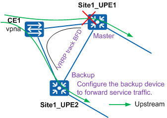
Deploy VRRP on two UPEs at a site to ensure reliability of uplink traffic on CEs. Site1 is used as an example, as shown in Figure 1.
Configure Site1_UPE1 as the master node and Site1_UPE2 as the backup node in a VRRP group. If Site1_UPE1 is faulty, uplink traffic on CE1 will be quickly switched to Site1_UPE2.
Configure BFD for VRRP so that hardware-based BFD can quickly detect faults. When a fault is detected, hardware notifies the backup device in a VRRP group to switch as the master device. Additionally, hardware directly sends gratuitous ARP packets to instruct devices at the access layer to forward traffic to the new master device.
Configure backup devices to forward service traffic. When the VRRP status of a device is Backup, the device can forward traffic as long as it receives traffic. This prevents service traffic loss and shortens service interruption time if the aggregation device is faulty.

If the number of VRRP groups exceeds the device default value, run the set vrrp max-group-number max-group-number command on the UPEs to set the maximum number of allowed VRRP groups.
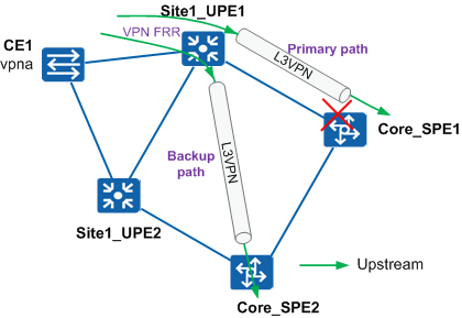
Deploy VPN FRR on a UPE. If the TE tunnel between the UPE and an SPE is faulty, traffic is automatically switched to the TE tunnel between the UPE and another SPE at the same site. Site1_UPE1 is used as an example, as shown in Figure 2.
Site1_UPE1 has two TE tunnels to Core_SPE1 and Core_SPE2 respectively. Deploying VPN FRR on Site1_UPE1 ensures that traffic is quickly switched to Core_SPE2 if Core_SPE1 is faulty.
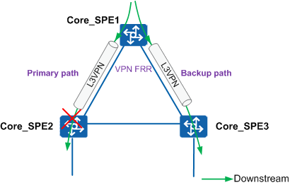
Deploy VPN FRR on an SPE, for example Core_SPE1. If Core_SPE2 connected to Core_SPE1 is faulty, Core_SPE1 switches VPN services to Core_SPE3, implementing fast E2E switchovers of VPN services, as shown in Figure 3.
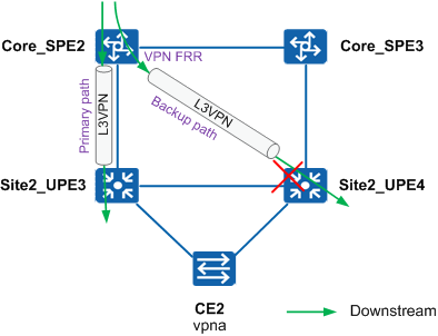
Deploy VPN FRR on an SPE. If the TE tunnel between the SPE and a UPE is faulty, traffic is automatically switched to the TE tunnel between the SPE and another UPE at the same site. Core_SPE2 is used as an example, as shown in Figure 4.
Core_SPE2 has two TE tunnels to Site2_UPE3 and Site2_UPE4 respectively. Deploying VPN FRR on Core_SPE2 ensures that traffic is quickly switched to Site2_UPE4 if Site2_UPE3 is faulty.
Deploy IP+VPN hybrid FRR on UPEs. If the interface of a UPE detects a fault on the link between the UPE and its connected CE, the UPE quickly switches traffic to its peer UPE, and the peer UPE then forwards the traffic to the CE. Site2 is used as an example, as shown in Figure 5.
If the link from Site2_UPE3 to CE2 is faulty, traffic is forwarded to Site2_UPE4 through an LSP and then to CE2 using a private IP address, improving network reliability.
Deploy VPN GR on all UPEs and SPEs to ensure uninterrupted VPN traffic forwarding during a master/backup switchover on the device transmitting VPN services.

Procedure
- Configure SPEs.
The following uses the configuration of Core_SPE1 on the core ring as an example. The configurations of Core_SPE2 and Core_SPE3 are similar to the configuration of Core_SPE1, and are not mentioned here.
bgp 65000
 graceful-restart    //Enable BGP GR.
 #
 ipv4-family vpnv4
  auto-frr    //Enable VPNv4 FRR.
  bestroute nexthop-resolved tunnel    //Configure the system to select a VPNv4 route only when the next hop is iterated to a tunnel, preventing packet loss during a revertive switchover.
 #
  ipv4-family vpn-instance vpna
  auto-frr    //Enable VPN auto FRR.
  vpn-route cross multipath    //Add multiple VPNv4 routes to a VPN instance with a different RD value from these routes' RD values, making VPN FRR take effect.
#
- Configure UPEs.
The following uses the configuration of Site1_UPE1 as an example. The configurations of Site1_UPE2, Site2_UPE3, Site2_UPE4, Site3_UPE5, and Site3_UPE6 are similar to the configuration of Site1_UPE1, and are not mentioned here.
ip vpn-instance vpna
 ipv4-family
  ip frr route-policy mixfrr    //Enable IP FRR.
#
interface XGigabitEthernet1/0/4.200
 vrrp vrid 1 virtual-ip 172.18.200.65    //Configure VRRP.
 vrrp vrid 1 preempt-mode timer delay 250    //Set the preemption delay of switches in a VRRP group.
 vrrp vrid 1 track bfd-session 2200 peer    //Enable BFD for VRRP to implement master/backup switchovers.
 vrrp vrid 1 backup-forward    //Enable the backup device to forward service traffic.
 vrrp track bfd gratuitous-arp send enable    //Enable BFD for VRRP to quickly send gratuitous ARP packets during master/backup switchovers.
#
bfd vrrp-1 bind peer-ip 172.18.200.67 vpn-instance vpna interface XGigabitEthernet1/0/4.200 source-ip 172.18.200.66    //Configure static BFD for VRRP.
 discriminator local 2200    //Set the local discriminator. The local discriminator of the local system must be the same as the remote discriminator of the remote system.
 discriminator remote 1200    //Set the remote discriminator.
 detect-multiplier 8    //Set the local detection multiplier of BFD.
 min-tx-interval 3    //Set the minimum interval at which the local device sends BFD packets to 3.3 ms.
 min-rx-interval 3    //Set the minimum interval at which the local device receives BFD packets to 3.3 ms.
 commit    //Commit the BFD session configuration.
#
bgp 65000
 graceful-restart
 #
 ipv4-family vpn-instance vpna
  auto-frr
 #
#
route-policy mixfrr permit node 0    //Set the backup next hop to the loopback interface 1 of another UPE at the same site.
 apply backup-nexthop 172.16.2.50
#
Checking the Configuration
Run the display ip routing-table vpn-instance command on SPEs to check the VPN FRR status from SPEs to UPEs.
The command output on Core_SPE2 is used as an example. The fields in boldface indicate the backup next hop, backup label, and backup tunnel ID. The command output shows that the hybrid FRR entry from Core_SPE2 to a UPE has been generated.
[Core_SPE2]display ip routing-table vpn-instance vpna 172.18.150.4 verbose
Route Flags: R - relay, D - download to fib, T - to vpn-instance
------------------------------------------------------------------------------
Routing Table : 1
Summary Count : 1

Destination: 172.18.150.0/26
     Protocol: IBGP             Process ID: 0
   Preference: 255                    Cost: 0
      NextHop: 172.16.2.75       Neighbour: 172.16.2.75
        State: Active Adv Relied       Age: 21h55m50s
          Tag: 0                  Priority: low
        Label: 1025                QoSInfo: 0x0
   IndirectID: 0x185
 RelayNextHop: 0.0.0.0           Interface: Tunnel111
     TunnelID: 0x2                   Flags: RD
    BkNextHop: 172.16.2.76     BkInterface: Tunnel121
      BkLabel: 1024            SecTunnelID: 0x0
 BkPETunnelID: 0x3         BkPESecTunnelID: 0x0
 BkIndirectID: 0xd
Run the display ip routing-table vpn-instance command on UPEs to check the hybrid FRR status.
The command output on Site2_UPE3 is used as an example. The fields in boldface indicate the backup next hop, backup label, and backup tunnel ID. The command output shows that the hybrid FRR entry has been generated. The command output shows that the master hybrid FRR route is to the local sub-interface, and the backup route is to the UPE with IP address 172.16.2.76 at the same site.
[Site2_UPE3]display ip routing-table vpn-instance vpna 172.18.150.4 verbose
Route Flags: R - relay, D - download to fib, T - to vpn-instance
------------------------------------------------------------------------------
Routing Table : 1
Summary Count : 2

Destination: 172.18.150.4/32
     Protocol: Direct           Process ID: 0
   Preference: 0                      Cost: 0
      NextHop: 172.18.150.4      Neighbour: 0.0.0.0
        State: Active Adv              Age: 1d02h36m21s
          Tag: 0                  Priority: high
        Label: NULL                QoSInfo: 0x0
   IndirectID: 0x0
 RelayNextHop: 0.0.0.0           Interface: XGigabitEthernet0/0/2.150
     TunnelID: 0x0                   Flags:  D
    BkNextHop: 172.16.2.76     BkInterface: XGigabitEthernet0/0/4
      BkLabel: 1024            SecTunnelID: 0x0
 BkPETunnelID: 0x4800001b  BkPESecTunnelID: 0x0
 BkIndirectID: 0x0

Destination: 172.18.150.4/32
     Protocol: IBGP             Process ID: 0
   Preference: 255                    Cost: 0
      NextHop: 172.16.2.76       Neighbour: 172.16.2.76
        State: Inactive Adv Relied     Age: 1d02h36m21s
          Tag: 0                  Priority: low
        Label: 1024                QoSInfo: 0x0
   IndirectID: 0xcd
 RelayNextHop: 172.16.8.181      Interface: XGigabitEthernet0/0/4
     TunnelID: 0x4800001b            Flags: R
Run the display vrrp interface command to check the VRRP status.
The command output on Site2_UPE3 is used as an example. The fields in boldface in the command output indicate that the VRRP status of Site2_UPE3 is Master, the backup device has been configured to forward service traffic, and BFD for VRRP has been configured.
[Site2_UPE3]display vrrp interface XGigabitEthernet0/0/2.150
  XGigabitEthernet0/0/2.150 | Virtual Router 1
    State : Master
    Virtual IP : 172.18.150.1
    Master IP : 172.18.150.2
    PriorityRun : 100
    PriorityConfig : 100
    MasterPriority : 100
    Preempt : YES   Delay Time : 250 s
    TimerRun : 1 s
    TimerConfig : 1 s
    Auth type : NONE
    Virtual MAC : 0000-5e00-0101
    Check TTL : YES
    Config type : normal-vrrp
    Backup-forward : enabled
    Track BFD : 1150  type: peer
    BFD-session state : UP
    Create time : 2016-05-21 11:02:27
    Last change time : 2016-05-21 11:02:55