Example for Configuring VRRP to Ensure Reliable Multicast Data Transmission
VRRP Overview
Generally, all hosts on the same network segment have the same default route with the gateway address as the next hop address. The hosts use the default route to send packets to the gateway and the gateway forwards the packets to other network segments. When the gateway fails, the hosts with the same default route cannot communicate with external networks. Configuring multiple egress gateways is a commonly used method to improve system reliability. However, route selection between the gateways becomes an issue.
VRRP solves the problem. VRRP virtualizes multiple routing devices into a virtual router without changing the networking, and uses the virtual router IP address as the default gateway address to implement gateway backup. When the gateway fails, VRRP selects a new gateway to transmit service traffic to ensure reliable communication.
Configuration Notes
- VRRP groups must use different virtual IP addresses. The virtual IP address of a VRRP group must be on the same network segment as the IP address of the interface where the VRRP group is configured.
- Ensure that each device of the same VRRP group is configured with the same VRID.
- In V200R003C00 and earlier versions, only the VLANIF interface supports VRRP. In V200R005C00 and later versions, VLANIF and Layer 3 Ethernet interfaces support VRRP.
For applicable product models and versions, see Applicable Product Models and Versions.

For details about software mappings, visit Hardware Query Tool and search for the desired product model.
Networking Requirements
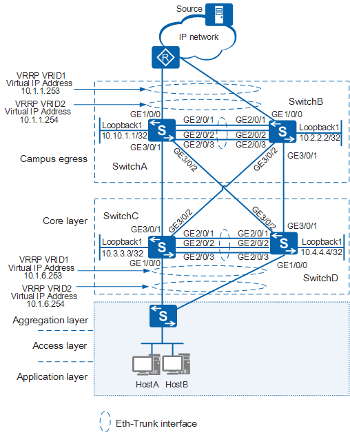
As shown in Figure 1, SwitchA and SwitchB are egress gateways of the campus network; SwitchC and SwitchD are core switches. The multicast source connects to the campus network through a router. Key nodes on the network work in redundancy mode to improve network reliability, and the egress gateways and core switches are fully meshed to implement link redundancy. The egress gateways and core switches must be configured to enable multicast data to be reliably transmitted to the downstream network.
In this scenario, to avoid loops, ensure that all connected interfaces have STP disabled and connected interfaces are removed from VLAN 1. If STP is enabled and VLANIF interfaces of switches are used to construct a Layer 3 ring network, an interface on the network will be blocked. As a result, Layer 3 services on the network cannot run normally.
Device |
Interface |
VLAN |
VLANIF Interface IP Address |
Device |
Interface |
VLAN |
VLANIF Interface IP Address |
|---|---|---|---|---|---|---|---|
SwitchA |
GE1/0/0 |
VLAN 100 |
10.1.1.1/24 |
SwitchC |
GE1/0/0 |
VLAN 400 |
10.1.6.1/24 |
Eth-trunk 1 (with member interfaces GE2/0/1, GE2/0/2, and GE2/0/3) |
VLAN 100, VLAN 200 |
No VLANIF 200 interface |
Eth-trunk 1(with member interfaces GE2/0/1, GE2/0/2, and GE2/0/3) |
VLAN 400, VLAN 500 |
No VLANIF 500 interface |
||
GE3/0/1 |
VLAN 301 |
10.1.2.1/24 |
GE3/0/1 |
VLAN 301 |
10.1.2.2/24 |
||
GE3/0/2 |
VLAN 302 |
10.1.3.1/24 |
GE3/0/2 |
VLAN 304 |
10.1.5.2/24 |
||
SwitchB |
GE1/0/0 |
VLAN 100 |
10.1.1.2/24 |
SwitchD |
GE1/0/0 |
VLAN 400 |
10.1.6.2/24 |
Eth-trunk 1 (with member interfaces GE2/0/1, GE2/0/2, and GE2/0/3) |
VLAN 100, VLAN 200 |
No VLANIF 200 interface |
Eth-trunk 1(with member interfaces GE2/0/1, GE2/0/2, and GE2/0/3) |
VLAN 400, VLAN 500 |
No VLANIF 500 interface |
||
GE3/0/1 |
VLAN 303 |
10.1.4.1/24 |
GE3/0/1 |
VLAN 303 |
10.1.4.2/24 |
||
GE3/0/2 |
VLAN 304 |
10.1.5.1/24 |
GE3/0/2 |
VLAN 302 |
10.1.3.2/24 |
Configuration Roadmap
To ensure reliable multicast data transmission, configure the Virtual Router Redundancy Protocol (VRRP) and Bidirectional Forwarding Detection (BFD) on the egress gateways and core switches. To ensure normal multicast forwarding, configure a multicast protocol on the egress gateways and core switches.
- Configure link aggregation groups between SwitchA and SwitchB, and between SwitchC and SwitchD to ensure fast and reliable exchange of VRRP packets.
- Create VLANs on the switches and add their interfaces to respective VLANs. Configure IP addresses for the corresponding VLANIF interfaces to make local network segments reachable.
- Configure the Open Shortest Path First (OSPF) protocol on the switches to ensure reachable routes between them. OSPF routes load balance unicast traffic between the egress gateways and core switches to reduce loads of links that transmit multicast and unicast data simultaneously.
- Configure a VRRP group between SwitchA and SwitchB and a VRRP group between SwitchC and SwitchD to ensure reliable multicast forwarding. The VRRP groups implement load balancing for unicast traffic to reduce loads of links that transmit multicast and unicast data simultaneously.
- Configure a multicast protocol on the switches to ensure normal multicast data forwarding.
- Configure BFD for OSPF and BFD for PIM on the switches to enable the switches to quickly detect link failures, realizing fast convergence of unicast and multicast routes.
Procedure
Configure link aggregation groups on the switches.
# Create Eth-Trunks and add member interfaces to the Eth-Trunks on the campus egress gateway and core devices.
<SwitchA> system-view
[SwitchA] interface Eth-Trunk1     //Create Eth-Trunk1 and bind member interfaces GE2/0/1 through GE2/0/3 to it.
[SwitchA-Eth-Trunk1] trunkport gigabitethernet 2/0/1 to 2/0/3
[SwitchA-Eth-Trunk1] quit
<SwitchB> system-view [SwitchB] interface Eth-Trunk1 //Create Eth-Trunk1 and bind member interfaces GE2/0/1 through GE2/0/3 to it. [SwitchB-Eth-Trunk1] trunkport gigabitethernet 2/0/1 to 2/0/3 [SwitchB-Eth-Trunk1] quit<SwitchC> system-view [SwitchC] interface Eth-Trunk1 //Create Eth-Trunk1 and bind member interfaces GE2/0/1 through GE2/0/3 to it. [SwitchC-Eth-Trunk1] trunkport gigabitethernet 2/0/1 to 2/0/3 [SwitchC-Eth-Trunk1] quit<SwitchD> system-view [SwitchD] interface Eth-Trunk1 //Create Eth-Trunk1 and bind member interfaces GE2/0/1 through GE2/0/3 to it. [SwitchD-Eth-Trunk1] trunkport gigabitethernet 2/0/1 to 2/0/3 [SwitchD-Eth-Trunk1] quitBy default, an Eth-Trunk works in manual load balancing mode, and all active interfaces load balance traffic.
Create VLANs, add interfaces to respective VLANs, and configure IP addresses for corresponding VLANIF interfaces.
Create VLANs and add interfaces to the VLANs on the campus egress gateway and core devices. The configurations on SwitchB, SwitchC, and SwitchD are similar to the configuration on SwitchA, and are not mentioned here.
The Spanning Tree Protocol (STP) is enabled on Layer 2 interfaces of a switch by default. On a Layer 2 ring network, STP blocks an interface to prevent loops. In this example, SwitchC, SwitchD, and the downstream Layer 2 switch form a Layer 2 ring network. To enable unicast traffic to be loaded balanced among OSPF routes, you are advised to disable STP on 's Layer 2 interfaces connected to the Layer 2 switch. Additionally, you can configure Smart Link on the Layer 2 switch to implement load balancing between uplinks while preventing broadcast storms on the Layer 2 ring network.
[SwitchA] vlan batch 100 200 301 302
[SwitchA] interface gigabitethernet 1/0/0
[SwitchA-GigabitEthernet1/0/0] port link-type trunk     //Set the link type of the interface to trunk, which is not the default link type.
[SwitchA-GigabitEthernet1/0/0] port trunk allow-pass vlan 100
[SwitchA-GigabitEthernet1/0/0] quit
[SwitchA] interface gigabitethernet 3/0/1
[SwitchA-GigabitEthernet3/0/1] port link-type trunk     //Set the link type of the interface to trunk, which is not the default link type.
[SwitchA-GigabitEthernet3/0/1] port trunk allow-pass vlan 301
[SwitchA-GigabitEthernet3/0/1] quit
[SwitchA] interface gigabitethernet 3/0/2
[SwitchA-GigabitEthernet3/0/2] port link-type trunk     //Set the link type of the interface to trunk, which is not the default link type.
[SwitchA-GigabitEthernet3/0/2] port trunk allow-pass vlan 302
[SwitchA-GigabitEthernet3/0/2] quit
[SwitchA] interface eth-trunk 1
[SwitchA-Eth-Trunk1] port link-type trunk     //Set the link type of the interface to trunk, which is not the default link type.
[SwitchA-Eth-Trunk1] port trunk allow-pass vlan 100 200
[SwitchA-Eth-Trunk1] quit
Configure IP addresses for Layer 3 interfaces on the campus egress gateway and core devices. The configurations on SwitchB, SwitchC, and SwitchD are similar to the configuration on SwitchA, and are not mentioned here.
[SwitchA] interface vlanif 100     //Create VLANIF100.
[SwitchA-Vlanif100] ip address 10.1.1.1 24
[SwitchA-Vlanif100] quit
[SwitchA] interface vlanif 301     //Create VLANIF301.
[SwitchA-Vlanif301] ip address 10.1.2.1 24
[SwitchA-Vlanif301] quit
[SwitchA] interface vlanif 302     //Create VLANIF302.
[SwitchA-Vlanif302] ip address 10.1.3.1 24
[SwitchA-Vlanif302] quit
[SwitchA] interface loopback 1     //Create LoopBack1.
[SwitchA-LoopBack1] ip address 10.10.1.1 32
[SwitchA-LoopBack1] quit
Configure OSPF.
# Enable OSPF on the campus egress gateway and core devices, add the devices to area 0, and advertise local network segments in area 0. The configurations on SwitchB, SwitchC, and SwitchD are similar to the configuration on SwitchA, and are not mentioned here.
[SwitchA] ospf
[SwitchA-ospf-1] area 0
[SwitchA-ospf-1-area-0.0.0.0] network 10.1.1.0 0.0.0.255     //Specify that the interface running OSPF is the one connected to the 10.1.1.0 network segment and that the interface belongs to Area 0.
[SwitchA-ospf-1-area-0.0.0.0] network 10.1.2.0 0.0.0.255     //Specify that the interface running OSPF is the one connected to the 10.1.2.0 network segment and that the interface belongs to Area 0.
[SwitchA-ospf-1-area-0.0.0.0] network 10.1.3.0 0.0.0.255     //Specify that the interface running OSPF is the one connected to the 10.1.3.0 network segment and that the interface belongs to Area 0.
[SwitchA-ospf-1-area-0.0.0.0] network 10.10.1.1 0.0.0.0     //Specify that the interface running OSPF is the one connected to the 10.10.1.1 network segment and that the interface belongs to Area 0.
[SwitchA-ospf-1-area-0.0.0.0] quit
[SwitchA-ospf-1] quit
Configure VRRP groups.
Create VRRP group 1 on campus egress gateway devices SwitchA and SwitchB. Set the priority of SwitchA to 120 and the preemption delay to 20 seconds. Retain the default priority of SwitchB. Therefore, SwitchA becomes the master device and SwitchB becomes the backup device of VRRP group 1.
# Configure SwitchA.
[SwitchA] interface vlanif 100
[SwitchA-Vlanif100] vrrp vrid 1 virtual-ip 10.1.1.253     //Create VRRP group 1 on VLANIF100 and set the virtual IP address of the VRRP group to 10.1.1.253.
[SwitchA-Vlanif100] vrrp vrid 1 priority 120     //Set the priority of VLANIF100 in VRRP group 1 to 120.
[SwitchA-Vlanif100] vrrp vrid 1 preempt-mode timer delay 20     //Set the preemption delay of VLANIF100 in VRRP group 1 to 20 seconds.
[SwitchA-Vlanif100] quit
# Configure SwitchB.
[SwitchB] interface vlanif 100
[SwitchB-Vlanif100] vrrp vrid 1 virtual-ip 10.1.1.253     //Create VRRP group 1 on VLANIF100 and set the virtual IP address of the VRRP group to 10.1.1.253.
[SwitchB-Vlanif100] quit
Create VRRP group 2 on campus egress gateway devices SwitchA and SwitchB. Set the priority of SwitchB to 120 and the preemption delay to 20 seconds. Retain the default priority of SwitchA. Therefore, SwitchB becomes the master device and SwitchA becomes the backup device of VRRP group 1.
# Configure SwitchA.
[SwitchA] interface vlanif 100
[SwitchA-Vlanif100] vrrp vrid 2 virtual-ip 10.1.1.254     //Create VRRP group 2 on VLANIF100 and set the virtual IP address of the VRRP group to 10.1.1.254.
[SwitchA-Vlanif100] quit
# Configure SwitchB.
[SwitchB] interface vlanif 100
[SwitchB-Vlanif100] vrrp vrid 2 virtual-ip 10.1.1.254     //Create VRRP group 2 on VLANIF100 and set the virtual IP address of the VRRP group to 10.1.1.254.
[SwitchB-Vlanif100] vrrp vrid 2 priority 120     //Set the priority of VLANIF100 in VRRP group 2 to 120.
[SwitchB-Vlanif100] vrrp vrid 2 preempt-mode timer delay 20     //Set the preemption delay of VLANIF100 in VRRP group 2 to 20 seconds.
[SwitchB-Vlanif100] quit
The configurations on SwitchC and SwitchD are similar to the configurations on SwitchA and SwitchB, and are not mentioned here.
Configure a multicast protocol.
Enable multicast routing on the campus egress gateway and core devices, and enable PIM-SM on their Layer 3 interfaces. Enable IGMP on user-side interfaces of the core devices.
# Configure SwitchA.
[SwitchA] multicast routing-enable     //Enable multicast routing globally.
[SwitchA] interface vlanif 100
[SwitchA-Vlanif100] pim sm     //Enable PIM-SM on VLANIF100.
[SwitchA-Vlanif100] quit
[SwitchA] interface vlanif 301
[SwitchA-Vlanif301] pim sm     //Enable PIM-SM on VLANIF301.
[SwitchA-Vlanif301] quit
[SwitchA] interface vlanif 302
[SwitchA-Vlanif302] pim sm     //Enable PIM-SM on VLANIF302.
[SwitchA-Vlanif302] quit
[SwitchA] interface loopback 1
[SwitchA-LoopBack1] pim sm     //Enable PIM-SM on LoopBack1.
[SwitchA-LoopBack1] quit
# Configure SwitchB.
[SwitchB] multicast routing-enable     //Enable multicast routing globally.
[SwitchB] interface vlanif 100
[SwitchB-Vlanif100] pim sm     //Enable PIM-SM on VLANIF100.
[SwitchB-Vlanif100] quit
[SwitchB] interface vlanif 303
[SwitchB-Vlanif303] pim sm     //Enable PIM-SM on VLANIF303.
[SwitchB-Vlanif303] quit
[SwitchB] interface vlanif 304
[SwitchB-Vlanif304] pim sm     //Enable PIM-SM on VLANIF304.
[SwitchB-Vlanif304] quit
[SwitchB] interface loopback 1
[SwitchB-LoopBack1] pim sm     //Enable PIM-SM on LoopBack1.
[SwitchB-LoopBack1] quit
# Configure SwitchC.
[SwitchC] multicast routing-enable     //Enable multicast routing globally.
[SwitchC] interface vlanif 400
[SwitchC-Vlanif400] pim sm     //Enable PIM-SM on VLANIF400.
[SwitchC-Vlanif400] igmp enable     //Enable PIM-SM on VLANIF400.
[SwitchC-Vlanif400] quit
[SwitchC] interface vlanif 301
[SwitchC-Vlanif301] pim sm     //Enable PIM-SM on VLANIF301.
[SwitchC-Vlanif301] quit
[SwitchC] interface vlanif 304
[SwitchC-Vlanif304] pim sm     //Enable PIM-SM on VLANIF304.
[SwitchC-Vlanif304] quit
[SwitchC] interface loopback 1
[SwitchC-LoopBack1] pim sm     //Enable PIM-SM on LoopBack1.
[SwitchC-LoopBack1] quit
# Configure SwitchD.
[SwitchD] multicast routing-enable     //Enable multicast routing globally.
[SwitchD] interface vlanif 400
[SwitchD-Vlanif400] pim sm     //Enable PIM-SM on VLANIF400.
[SwitchD-Vlanif400] igmp enable     //Enable IGMP on VLANIF400.
[SwitchD-Vlanif400] quit
[SwitchD] interface vlanif 302
[SwitchD-Vlanif302] pim sm     //Enable PIM-SM on VLANIF302.
[SwitchD-Vlanif302] quit
[SwitchD] interface vlanif 303
[SwitchD-Vlanif303] pim sm     //Enable PIM-SM on VLANIF303.
[SwitchD-Vlanif303] quit
[SwitchD] interface loopback 1
[SwitchD-LoopBack1] pim sm     //Enable PIM-SM on LoopBack1.
[SwitchD-LoopBack1] quit
Configure dynamic RP function on the core devices SwitchC and SwitchD that aggregate multicast traffic.
# Configure Loopback1 of SwitchC as a C-BSR and a C-RP.
[SwitchC] pim
[SwitchC-pim] c-bsr loopback 1     //Configure Loopback1 as a C-BSR interface.
[SwitchC-pim] c-rp loopback 1     //Configure Loopback1 as a C-RP interface.
[SwitchC-pim] quit
# Configure Loopback1 of SwitchD as a C-BSR and a C-RP.
[SwitchD] pim
[SwitchD-pim] c-bsr loopback 1     //Configure Loopback1 as a C-BSR interface.
[SwitchD-pim] c-rp loopback 1     //Configure Loopback1 as a C-RP interface.
[SwitchD-pim] quit
Configure BFD.
Enable global BFD on the campus egress gateway and core devices. Global BFD must be enabled before you configure BFD for OSPF and BFD for PIM. The configurations on SwitchB, SwitchC, and SwitchD are similar to the configuration on SwitchA, and are not mentioned here.
[SwitchA] bfd     //Enable BFD globally.
[SwitchA-bfd] quit
Enable BFD for OSPF on the campus egress gateway and core devices. The configurations on SwitchB, SwitchC, and SwitchD are similar to the configuration on SwitchA, and are not mentioned here.
[SwitchA] interface vlanif 100
[SwitchA-Vlanif100] ospf bfd enable     //Enable BFD for OSPF on VLANIF100.
[SwitchA-Vlanif100] quit
[SwitchA] interface vlanif 301
[SwitchA-Vlanif301] ospf bfd enable     //Enable BFD for OSPF on VLANIF301.
[SwitchA-Vlanif301] quit
[SwitchA] interface vlanif 302
[SwitchA-Vlanif302] ospf bfd enable     //Enable BFD for OSPF on VLANIF302.
[SwitchA-Vlanif302] quit
Enable BFD for PIM on the campus egress gateway and core devices. The configurations on SwitchB, SwitchC, and SwitchD are similar to the configuration on SwitchA, and are not mentioned here.
[SwitchA] interface vlanif 100
[SwitchA-Vlanif100] pim bfd enable     //Enable BFD for PIM on VLANIF100.
[SwitchA-Vlanif100] quit
[SwitchA] interface vlanif 301
[SwitchA-Vlanif301] pim bfd enable     //Enable BFD for PIM on VLANIF301.
[SwitchA-Vlanif301] quit
[SwitchA] interface vlanif 302
[SwitchA-Vlanif302] pim bfd enable     //Enable BFD for PIM on VLANIF302.
[SwitchA-Vlanif302] quit
Verify the configuration.
Verify the configuration of link aggregation.
# Run the display eth-trunk 1 command on SwitchA. The command output shows that Eth-Trunk 1 has three member interfaces: GigabitEthernet2/0/1, GigabitEthernet2/0/2, and GigabitEthernet2/0/3. All the member interfaces are Up.
[SwitchA] display eth-trunk 1
Eth-Trunk1's state information is:
WorkingMode: NORMAL          Hash arithmetic: According to SIP-XOR-DIP
Least Active-linknumber: 1     Max Bandwidth-affected-linknumber: 8
Operate status: up             Number Of Up Ports In Trunk: 3
--------------------------------------------------------------------------------
PortName                           Status       Weight
GigabitEthernet2/0/1               Up           1
GigabitEthernet2/0/2               Up           1
GigabitEthernet2/0/3               Up           1
The display eth-trunk 1 command outputs on SwitchB, SwitchC, and SwitchD are similar to the command output on SwitchA.
Verify the VRRP configuration.
# Run the display vrrp command on SwitchA. The command output shows that SwitchA is the master device in VRRP group 1 and the backup device in VRRP group 2.
[SwitchA] display vrrp
Vlanif100 | Virtual Router 1
    State : Master
    Virtual IP : 10.1.1.253
    Master IP : 10.1.1.1
    PriorityRun : 120
    PriorityConfig : 120
    MasterPriority : 120
    Preempt : YES   Delay Time : 20 s
    TimerRun : 1 s
    TimerConfig : 1 s
    Auth type : NONE
    Virtual MAC : 0000-5e00-0101
    Check TTL : YES
    Config type : normal-vrrp
    Backup-forward : disabled
    Create time : 2012-12-31 10:34:23 UTC-08:00
    Last change time : 2012-12-31 10:34:26 UTC-08:00

  Vlanif100 | Virtual Router 2
    State : Backup
    Virtual IP : 10.1.1.254
    Master IP : 10.1.1.2
    PriorityRun : 100
    PriorityConfig : 100
    MasterPriority : 120
    Preempt : YES   Delay Time : 0 s
    TimerRun : 1 s
    TimerConfig : 1 s
    Auth type : NONE
    Virtual MAC : 0000-5e00-0102
    Check TTL : YES
    Config type : normal-vrrp
    Backup-forward : disabled
    Create time : 2012-12-31 10:35:39 UTC-08:00
    Last change time : 2012-12-31 10:35:43 UTC-08:00
# Run the display vrrp command on SwitchB. The command output shows that SwitchB is the backup device in VRRP group 1 and the master device in VRRP group 2.
[SwitchB] display vrrp
Vlanif100 | Virtual Router 1
    State : Backup
    Virtual IP : 10.1.1.253
    Master IP : 10.1.1.1
    PriorityRun : 100
    PriorityConfig : 100
    MasterPriority : 120
    Preempt : YES   Delay Time : 0 s
    TimerRun : 1 s
    TimerConfig : 1 s
    Auth type : NONE
    Virtual MAC : 0000-5e00-0101
    Check TTL : YES
    Config type : normal-vrrp
    Backup-forward : disabled
    Create time : 2012-12-31 10:34:23 UTC-08:00
    Last change time : 2012-12-31 10:34:26 UTC-08:00

  Vlanif100 | Virtual Router 2
    State : Master
    Virtual IP : 10.1.1.254
    Master IP : 10.1.1.2
    PriorityRun : 120
    PriorityConfig : 120
    MasterPriority : 120
    Preempt : YES   Delay Time : 20 s
    TimerRun : 1 s
    TimerConfig : 1 s
    Auth type : NONE
    Virtual MAC : 0000-5e00-0102
    Check TTL : YES
    Config type : normal-vrrp
    Backup-forward : disabled
    Create time : 2012-12-31 10:35:39 UTC-08:00
    Last change time : 2012-12-31 10:35:43 UTC-08:00
The display vrrp command outputs on SwitchC and SwitchD are similar to the command outputs on SwitchA and SwitchB.
Verify the OSPF configuration.
# Run the display ip routing-table command on SwitchA. The command output shows that there are two IP routes to 10.1.6.0/24, implementing load balancing of unicast traffic.
[SwitchA] display ip routing-table
Route Flags: R - relay, D - download to fib, T - to vpn-instance
------------------------------------------------------------------------------
Routing Tables: Public
         Destinations : 15       Routes : 18

Destination/Mask    Proto   Pre  Cost      Flags NextHop         Interface

       10.1.1.0/24  Direct  0    0           D   10.1.1.1        Vlanif100
       10.1.1.1/32  Direct  0    0           D   127.0.0.1       Vlanif100
     10.1.1.253/32  Direct  0    0           D   127.0.0.1       Vlanif100
     10.1.1.254/32  Direct  0    0           D   127.0.0.1       Vlanif100
       10.1.2.0/24  Direct  0    0           D   10.1.2.1        Vlanif301
       10.1.2.1/32  Direct  0    0           D   127.0.0.1       Vlanif301
       10.1.3.0/24  Direct  0    0           D   10.1.3.1        Vlanif302
       10.1.3.1/32  Direct  0    0           D   127.0.0.1       Vlanif302
       10.1.4.0/24  OSPF    10   2           D   10.1.3.2        Vlanif302
       10.1.5.0/24  OSPF    10   2           D   10.1.2.2        Vlanif301
     10.1.6.0/24  OSPF    10   2           D   10.1.2.2        Vlanif301
                    OSPF    10   2           D   10.1.3.2        Vlanif302
     10.1.6.253/32  OSPF    10   2           D   10.1.2.2        Vlanif301
                    OSPF    10   2           D   10.1.3.2        Vlanif302
     10.1.6.254/32  OSPF    10   2           D   10.1.3.2        Vlanif302
                    OSPF    10   2           D   10.1.2.2        Vlanif301
      127.0.0.0/8   Direct  0    0           D   127.0.0.1       InLoopBack0
      127.0.0.1/32  Direct  0    0           D   127.0.0.1       InLoopBack0
The display ip routing-table command outputs on SwitchB, SwitchC, and SwitchD are similar to the command output on SwitchA.
Verify PIM-SM configuration.
Multicast source 10.100.1.1 sends multicast data to group 225.0.0.10, and user hosts have joined group 225.0.0.10.
# Run the display pim routing-table command on SwitchB and SwitchD. The command output shows that PIM routing entries have been created for group 225.0.0.10.
SwitchB and SwitchD implement multicast routing as follows:
- According to the dynamic RP election rules, C-RP interfaces have the same IP address mask, priority, and hash calculation result, the C-RP interface with a larger IP address becomes the RP. Therefore, Loopback1 of SwitchD becomes the RP interface.
- According to the reverse path check (RPF) rules, if two equal-cost optimal routes are available in the IP routing table, the one with a larger next hop address is selected as the RPF route. Therefore, SwitchD selects the route with the next hop address 10.1.5.1 as the RPF route to the destination network segment 10.1.1.0/24.
[SwitchB] display pim routing-table
VPN-Instance: public net
 Total 0 (*, G) entry; 1 (S, G) entry

 (10.100.1.1, 225.0.0.10)
     RP: 10.4.4.4
     Protocol: pim-sm, Flag: SPT ACT
     UpTime: 00:00:42
     Upstream interface: Vlanif100
         Upstream neighbor: 10.1.1.3
         RPF prime neighbor: 10.1.1.3
     Downstream interface(s) information:
     Total number of downstreams: 1
         1: Vlanif303
             Protocol: pim-sm, UpTime: 00:00:42, Expires:-
[SwitchD] display pim routing-table
VPN-Instance: public net
 Total 0 (*, G) entry; 1 (S, G) entry

 (10.100.1.1, 225.0.0.10)
     RP: 10.4.4.4
     Protocol: pim-sm, Flag: SPT ACT
     UpTime: 00:00:42
     Upstream interface: Vlanif303
         Upstream neighbor: 10.1.4.1
         RPF prime neighbor: 10.1.4.1
     Downstream interface(s) information:
     Total number of downstreams: 1
         1: Vlanif400
             Protocol: pim-sm, UpTime: 00:00:42, Expires:-
Verify the BFD configuration.
# Run the display ospf bfd session all command on SwitchA. The command output shows that OSPF BFD sessions have been successfully set up.
[SwitchA] display ospf bfd session all
OSPF Process 1 with Router ID 10.10.1.1

  Area 0.0.0.0 interface 10.1.1.1(Vlanif100)'s BFD Sessions

 NeighborId:10.2.2.2          AreaId:0.0.0.0          Interface: Vlanif100
 BFDState:up                 rx    :1000             tx       :1000
 Multiplier:3                BFD Local Dis:8196      LocalIpAdd:10.1.1.1
 RemoteIpAdd:10.1.1.2         Diagnostic Info:No diagnostic information

  Area 0.0.0.0 interface 10.1.1.1(Vlanif100)'s BFD Sessions

 NeighborId:5.5.5.5          AreaId:0.0.0.0          Interface: Vlanif100
 BFDState:up                 rx    :1000             tx       :1000
 Multiplier:4                BFD Local Dis:8195      LocalIpAdd:10.1.1.1
 RemoteIpAdd:10.1.1.3         Diagnostic Info:No diagnostic information

  Area 0.0.0.0 interface 10.1.2.1(Vlanif301)'s BFD Sessions

 NeighborId:10.3.3.3          AreaId:0.0.0.0          Interface: Vlanif301
 BFDState:up                 rx    :1000              tx       :1000
 Multiplier:3                BFD Local Dis:8194      LocalIpAdd:10.1.1.1
 RemoteIpAdd:10.1.2.2         Diagnostic Info:No diagnostic information

  Area 0.0.0.0 interface 10.1.3.1(Vlanif302)'s BFD Sessions

 NeighborId:10.4.4.4          AreaId:0.0.0.0          Interface: Vlanif302
 BFDState:up                 rx    :1000              tx       :1000
 Multiplier:3                BFD Local Dis:8193      LocalIpAdd:10.1.1.1
 RemoteIpAdd:10.1.3.2         Diagnostic Info:No diagnostic information
The display ospf bfd session all command outputs on SwitchB, SwitchC, and SwitchD are similar to the command output on SwitchA.
# Run the display pim bfd session command on SwitchA. The command output shows that PIM BFD sessions have been successfully set up.
[SwitchA] display pim bfd session
VPN-Instance: public net
Total 4 BFD session Created

Vlanif100 (10.1.1.1): Total 2 BFD session Created

Neighbor     ActTx(ms)     ActRx(ms)     ActMulti     Local/Remote     State
10.1.1.2     1000           1000           3            8192/8192       Up
10.1.1.3     1000           1000           3            8191/8191       Up

Vlanif301 (10.1.2.1): Total 1 BFD session Created

Neighbor     ActTx(ms)     ActRx(ms)     ActMulti     Local/Remote     State
10.1.2.2     1000           1000           3            8193/8193       Up

Vlanif302 (10.1.3.1): Total 1 BFD session Created

Neighbor     ActTx(ms)     ActRx(ms)     ActMulti     Local/Remote     State
10.1.3.2     1000           1000           3            8194/8194       Up
The display pim bfd session command outputs on SwitchB, SwitchC, and SwitchD are similar to the command output on SwitchA.
Configuration Files
Configuration file of campus egress gateway SwitchA
#
sysname SwitchA
#
vlan batch 100 200 301 to 302
#
multicast routing-enable
#
bfd
#
interface Vlanif100
 ip address 10.1.1.1 255.255.255.0
 vrrp vrid 1 virtual-ip 10.1.1.253
 vrrp vrid 1 priority 120
 vrrp vrid 1 preempt-mode timer delay 20
 vrrp vrid 2 virtual-ip 10.1.1.254
 pim sm
 pim bfd enable
 ospf bfd enable
#
interface Vlanif301
 ip address 10.1.2.1 255.255.255.0
 pim sm
 pim bfd enable
 ospf bfd enable
#
interface Vlanif302
 ip address 10.1.3.1 255.255.255.0
 pim sm
 pim bfd enable
 ospf bfd enable
#
interface Eth-Trunk1
 port link-type trunk
 port trunk allow-pass vlan 100 200
#
interface GigabitEthernet1/0/0
 port link-type trunk
 port trunk allow-pass vlan 100
#
interface GigabitEthernet2/0/1
 eth-trunk 1
#
interface GigabitEthernet2/0/2
 eth-trunk 1
#
interface GigabitEthernet2/0/3
 eth-trunk 1
#
interface GigabitEthernet3/0/1
 port link-type trunk
 port trunk allow-pass vlan 301
#
interface GigabitEthernet3/0/2
 port link-type trunk
 port trunk allow-pass vlan 302
#
interface LoopBack1
 ip address 10.10.1.1 255.255.255.255
 pim sm
#
ospf 1
 area 0.0.0.0
  network 10.1.1.0 0.0.0.255
  network 10.1.2.0 0.0.0.255
  network 10.1.3.0 0.0.0.255
  network 10.10.1.1 0.0.0.0
#
return
Configuration file of campus egress gateway SwitchB
#
sysname SwitchB
#
vlan batch 100 200 303 to 304
#
multicast routing-enable
#
bfd
#
interface Vlanif100
 ip address 10.1.1.2 255.255.255.0
 vrrp vrid 1 virtual-ip 10.1.1.253
 vrrp vrid 2 virtual-ip 10.1.1.254
 vrrp vrid 2 priority 120
 vrrp vrid 2 preempt-mode timer delay 20
 pim sm
 pim bfd enable
 ospf bfd enable
#
interface Vlanif303
 ip address 10.1.4.1 255.255.255.0
 pim sm
 pim bfd enable
 ospf bfd enable
#
interface Vlanif304
 ip address 10.1.5.1 255.255.255.0
 pim sm
 pim bfd enable
 ospf bfd enable
#
interface Eth-Trunk1
 port link-type trunk
 port trunk allow-pass vlan 100 200
#
interface GigabitEthernet1/0/0
 port link-type trunk
 port trunk allow-pass vlan 100
#
interface GigabitEthernet2/0/1
 eth-trunk 1
#
interface GigabitEthernet2/0/2
 eth-trunk 1
#
interface GigabitEthernet2/0/3
 eth-trunk 1
#
interface GigabitEthernet3/0/1
 port link-type trunk
 port trunk allow-pass vlan 303
#
interface GigabitEthernet3/0/2
 port link-type trunk
 port trunk allow-pass vlan 304
#
interface LoopBack1
 ip address 10.2.2.2 255.255.255.255
 pim sm
#
ospf 1
 area 0.0.0.0
  network 10.1.1.0 0.0.0.255
  network 10.1.4.0 0.0.0.255
  network 10.1.5.0 0.0.0.255
  network 10.2.2.2 0.0.0.0
#
return
Configuration file of core device SwitchC
#
sysname SwitchC
#
vlan batch 301 304 400 500
#
multicast routing-enable
#
bfd
#
interface Vlanif301
 ip address 10.1.2.2 255.255.255.0
 pim sm
 pim bfd enable
 ospf bfd enable
#
interface Vlanif304
 ip address 10.1.5.2 255.255.255.0
 pim sm
 pim bfd enable
 ospf bfd enable
#
interface Vlanif400
 ip address 10.1.6.1 255.255.255.0
 vrrp vrid 1 virtual-ip 10.1.6.253
 vrrp vrid 1 priority 120
 vrrp vrid 1 preempt-mode timer delay 20
 vrrp vrid 2 virtual-ip 10.1.6.254
 pim sm
 pim bfd enable
 igmp enable
 ospf bfd enable
#
interface Eth-Trunk1
 port link-type trunk
 port trunk allow-pass vlan 400 500
#
interface GigabitEthernet1/0/0
 port link-type trunk
 port trunk allow-pass vlan 400
 stp disable
#
interface GigabitEthernet2/0/1
 eth-trunk 1
#
interface GigabitEthernet2/0/2
 eth-trunk 1
#
interface GigabitEthernet2/0/3
 eth-trunk 1
#
interface GigabitEthernet3/0/1
 port link-type trunk
 port trunk allow-pass vlan 301
#
interface GigabitEthernet3/0/2
 port link-type trunk
 port trunk allow-pass vlan 304
#
interface LoopBack1
 ip address 10.3.3.3 255.255.255.255
 pim sm
#
ospf 1
 area 0.0.0.0
  network 10.1.2.0 0.0.0.255
  network 10.1.5.0 0.0.0.255
  network 10.1.6.0 0.0.0.255
  network 10.3.3.3 0.0.0.0
#
pim
 c-bsr LoopBack1
 c-rp LoopBack1
#
return
Configuration file of core device SwitchD
#
sysname SwitchD
#
vlan batch 302 to 303 400 500
#
multicast routing-enable
#
bfd
#
interface Vlanif302
 ip address 10.1.3.2 255.255.255.0
 pim sm
 pim bfd enable
 ospf bfd enable
#
interface Vlanif303
 ip address 10.1.4.2 255.255.255.0
 pim sm
 pim bfd enable
 ospf bfd enable
#
interface Vlanif400
 ip address 10.1.6.2 255.255.255.0
 vrrp vrid 1 virtual-ip 10.1.6.253
 vrrp vrid 2 virtual-ip 10.1.6.254
 vrrp vrid 2 priority 120
 vrrp vrid 2 preempt-mode timer delay 20
 pim sm
 pim bfd enable
 igmp enable
 ospf bfd enable
#
interface Eth-Trunk1
 port link-type trunk
 port trunk allow-pass vlan 400 500
#
interface GigabitEthernet1/0/0
 port link-type trunk
 port trunk allow-pass vlan 400
 stp disable
#
interface GigabitEthernet2/0/1
 eth-trunk 1
#
interface GigabitEthernet2/0/2
 eth-trunk 1
#
interface GigabitEthernet2/0/3
 eth-trunk 1
#
interface GigabitEthernet3/0/1
 port link-type trunk
 port trunk allow-pass vlan 303
#
interface GigabitEthernet3/0/2
 port link-type trunk
 port trunk allow-pass vlan 302
#
interface LoopBack1
 ip address 10.4.4.4 255.255.255.255
 pim sm
#
ospf 1
 area 0.0.0.0
  network 10.1.3.0 0.0.0.255
  network 10.1.4.0 0.0.0.255
  network 10.1.6.0 0.0.0.255
  network 10.4.4.4 0.0.0.0
#
pim
 c-bsr LoopBack1
 c-rp LoopBack1
#
return
Applicable Product Models and Versions
Product |
Product Model |
Software Version |
|---|---|---|
S3700 |
S3700-EI |
V100R006C05 |
S3700-HI |
V200R001C00 |
|
S5700 |
S5720-SI, S5720S-SI |
V200R008C00, V200R009C00, V200R010C00, V200R011C00, V200R011C10, V200R012C00, V200R013C00, V200R019C00, V200R019C10 |
S5720I-SI |
V200R012C00, V200R013C00, V200R019C00, V200R019C10 |
|
S5730-SI |
V200R011C10, V200R012C00, V200R013C00, V200R019C00, V200R019C10 |
|
S5730S-EI |
V200R011C10, V200R012C00, V200R013C00, V200R019C00, V200R019C10 |
|
S5700-EI |
V200R001(C00&C01), V200R002C00, V200R003C00, V200R005(C00&C01&C02&C03) |
|
S5710-EI |
V200R001C00, V200R002C00, V200R003C00, V200R005(C00&C02) |
|
S5720-EI |
V200R007C00, V200R008C00, V200R009C00, V200R010C00, V200R011C00, V200R011C10, V200R012C00, V200R013C00, V200R019C00, V200R019C10 |
|
S5700-HI |
V200R001(C00&C01), V200R002C00, V200R003C00, V200R005(C00SPC500&C01&C02) |
|
S5710-HI |
V200R003C00, V200R005(C00&C02&C03) |
|
S5720-HI |
V200R006C00, V200R007(C00&C10), V200R008C00, V200R009C00, V200R010C00, V200R011C00, V200R011C10, V200R012C00, V200R013C00, V200R019C00, V200R019C10 |
|
S5730-HI |
V200R012C00, V200R013C00, V200R019C00, V200R019C10 |
|
S5731-H |
V200R013C02, V200R019C00, V200R019C10 |
|
S5731-S, S5731S-S |
V200R019C00, V200R019C10 |
|
S5731S-H |
V200R019C00, V200R019C10 |
|
S5732-H |
V200R019C00, V200R019C10 |
|
S5735-S, S5735S-S |
V200R019C00, V200R019C10 |
|
S5700 |
S5735-S-I |
V200R019C10 |
S6700 |
S6700-EI |
V200R001(C00&C01), V200R002C00, V200R003C00, V200R005(C00&C01&C02) |
S6720-EI |
V200R008C00, V200R009C00, V200R010C00, V200R011C00, V200R011C10, V200R012C00, V200R013C00, V200R019C00, V200R019C10 |
|
S6720S-EI |
V200R009C00, V200R010C00, V200R011C00, V200R011C10, V200R012C00, V200R013C00, V200R019C00, V200R019C10 |
|
S6720-SI, S6720S-SI |
V200R011C00, V200R011C10, V200R012C00, V200R013C00, V200R019C00, V200R019C10 |
|
S6720-HI |
V200R012C00, V200R013C00, V200R019C00, V200R019C10 |
|
S6730-H |
V200R013C02, V200R019C00, V200R019C10 |
|
S6730S-H |
V200R019C10 |
|
S6730-S, S6730S-S |
V200R019C00, V200R019C10 |
|
S7700 |
S7703, S7706, S7712 |
V200R001(C00&C01), V200R002C00, V200R003C00, V200R005C00, V200R006C00, V200R007C00, V200R008C00, V200R009C00, V200R010C00, V200R011C10, V200R012C00, V200R013C00, V200R013C02, V200R019C00, V200R019C10 |
S7703 PoE |
V200R013C00, V200R019C00, V200R019C10 |
|
S7706 PoE |
V200R013C00, V200R019C00, V200R019C10 |
|
S9700 |
S9703, S9706, S9712 |
V200R001(C00&C01), V200R002C00, V200R003C00, V200R005C00, V200R006C00, V200R007(C00&C10), V200R008C00, V200R009C00, V200R010C00, V200R011C10, V200R012C00, V200R013C00 |