Example for Configuring Multiple Authentication Modes to Control User Access
Overview of Multiple Authentication Modes
In NAC network deployment, to provide flexible authentication, the device supports concurrent deployment of 802.1X authentication, MAC address authentication, and Portal authentication on the interfaces connected to users. In this case, the users can access the network using any authentication mode.
If multiple authentication modes are enabled, the authentication modes take effect in the sequence they are configured. In addition, after multiple authentication modes are deployed, users can be authenticated in different modes by default and assigned different network rights accordingly by the device.
Configuration Notes
This configuration example applies to all switches running all versions.
When you run the access-user arp-detect command to configure the IP address and MAC address of the user gateway as the source IP address and source MAC address of user offline detection packets, ensure that the MAC address of the gateway remains unchanged, especially in active/standby switchover scenarios. If the gateway MAC address is changed, ARP entries of terminals will be incorrect on the device, and the terminals cannot communicate with the device.
Networking Requirements
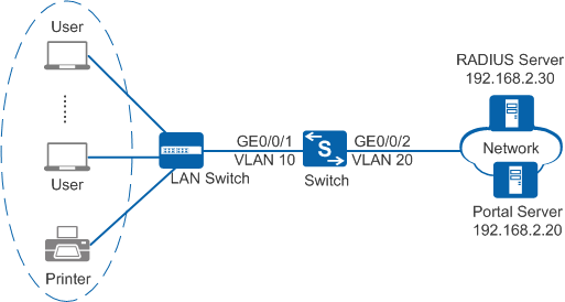
As shown in Figure 1, the terminals in a company are connected to the company's internal network through the Switch. Unauthorized access to the internal network can damage the company's service system and cause leakage of key information. Therefore, the administrator requires that the Switch should control the users' network access rights to ensure internal network security.
Configuration Roadmap
The configuration roadmap is as follows:
- Create and configure a RADIUS server template, an AAA scheme, and an authentication domain. Bind the RADIUS server template and AAA scheme to the authentication domain so that the Switch can authenticate access users through the RADIUS server.
- Enable 802.1X authentication, MAC address authentication, and Portal authentication so that the Switch can control network access rights of the internal employees, dumb terminals, and visitors. In addition, configure 802.1X authentication to take precedence because there are more employees than dumb terminals and visitors.
- Configure the user access mode to multi-authen and set the maximum number of access users to 100, so the device can control the network access rights of each user independently.
- Configure a Portal server template so that the device can communicate with the Portal server.

Before configuring this example, ensure that devices can communicate with each other on the network.
Procedure
- Create VLANs and configure the VLANs allowed by the interface to ensure network communication.
# Create VLAN 10 and VLAN 20.
<HUAWEI> system-view
[HUAWEI] sysname Switch
[Switch] vlan batch 10 20
# On the Switch, configure the interface GE0/0/1 connected to users as an access interface and add the interface to VLAN 10.
[Switch] interface gigabitethernet0/0/1
[Switch-GigabitEthernet0/0/1] port link-type access
[Switch-GigabitEthernet0/0/1] port default vlan 10
[Switch-GigabitEthernet0/0/1] quit
[Switch] interface vlanif 10
[Switch-Vlanif10] ip address 192.168.1.10 24
[Switch-Vlanif10] quit
Configure the interface type and VLANs based on the site requirements. In this example, users are added to VLAN 10.
# On the Switch, configure the interface GE0/0/2 connected to the RADIUS server as an access interface and add the interface to VLAN 20.
[Switch] interface gigabitethernet0/0/2
[Switch-GigabitEthernet0/0/2] port link-type access
[Switch-GigabitEthernet0/0/2] port default vlan 20
[Switch-GigabitEthernet0/0/2] quit
- Create and configure a RADIUS server template, an AAA scheme, and an authentication domain.
# Create and configure the RADIUS server template rd1.
[Switch] radius-server template rd1
[Switch-radius-rd1] radius-server authentication 192.168.2.30 1812
[Switch-radius-rd1] radius-server shared-key cipher Huawei@2012
[Switch-radius-rd1] quit
# Create an AAA authentication scheme abc and configure the authentication mode to RADIUS.
[Switch] aaa
[Switch-aaa] authentication-scheme abc
[Switch-aaa-authen-abc] authentication-mode radius
[Switch-aaa-authen-abc] quit
# Create an authentication domain isp1, and bind the AAA scheme abc and RADIUS server template rd1 to the domain isp1.
[Switch-aaa] domain isp1
[Switch-aaa-domain-isp1] authentication-scheme abc
[Switch-aaa-domain-isp1] radius-server rd1
[Switch-aaa-domain-isp1] quit
[Switch-aaa] quit
# Configure isp1 as the global default domain. During access authentication, enter a user name in the format user@isp1 to perform AAA authentication in the domain isp1. If the user name does not contain the domain name or contains an invalid domain name, the user is authenticated in the default domain.
[Switch] domain isp1 - Configure 802.1X authentication, MAC address authentication, and Portal authentication on the Switch.# Switch the NAC mode to unified mode.
[Switch] authentication unified-mode After the common mode and unified mode are switched, the device automatically restarts.
# Enable 802.1X authentication, MAC address authentication, and Portal authentication on the interface GE0/0/1.
[Switch] interface gigabitethernet0/0/1
[Switch-GigabitEthernet0/0/1] authentication dot1x mac-authen portal
[Switch-GigabitEthernet0/0/1] authentication mode multi-authen max-user 100
[Switch-GigabitEthernet0/0/1] quit
# Create and configure a Portal server template abc.[Switch] web-auth-server abc [Switch-web-auth-server-abc] server-ip 192.168.2.20 [Switch-web-auth-server-abc] port 50200 [Switch-web-auth-server-abc] url http://192.168.2.20:8080/webagent [Switch-web-auth-server-abc] shared-key cipher Huawei@123 [Switch-web-auth-server-abc] quit
Ensure that the port number configured on the device is the same as that used by the Portal server.
# Bind the Portal server template abc to the interface GE0/0/1.[Switch] interface gigabitethernet0/0/1 [Switch-GigabitEthernet0/0/1] web-auth-server abc direct [Switch-GigabitEthernet0/0/1] quit
# (Recommended) Configure the source IP address and source MAC address for offline detection packets in a specified VLAN. You are advised to set the user gateway IP address and its corresponding MAC address as the source IP address and source MAC address of offline detection packets. This function does not take effect for users who use Layer 3 Portal authentication.
[Switch] access-user arp-detect vlan 10 ip-address 192.168.1.10 mac-address 2222-1111-1234 - Verify the configuration.
- Run the display dot1x, display mac-authen, display portal, and display web-auth-server configuration commands. The command outputs show that 802.1X authentication, MAC address authentication, and Portal authentication have been enabled on GE0/0/1.
- The user can access the network after passing 802.1X authentication, MAC address authentication, or Portal authentication.
- After the user goes online, you can run the display access-user interface gigabitethernet0/0/1 command on the device to check all online user information.
Configuration Files
Configuration file of the Switch
#
sysname Switch
#
vlan batch 10 20
#
domain isp1 #
radius-server template rd1
 radius-server shared-key cipher %^%#Q75cNQ6IF(e#L4WMxP~%^7'u17,]D87GO{"[o]`D%^%#
 radius-server authentication 192.168.2.30 1812 weight 80#
web-auth-server abc
 server-ip 192.168.2.20
 port 50200
 shared-key cipher %^%#t:hJ@gD7<+G&,"Y}Y[VP4\foQ&og/Gg(,J4#\!gD%^%#
 url http://192.168.2.20:8080/webagent
#
aaa
 authentication-scheme abc
  authentication-mode radius
 domain isp1
  authentication-scheme abc
  radius-server rd1#
interface Vlanif10
 ip address 192.168.1.10 255.255.255.0
#
interface GigabitEthernet0/0/1
 port link-type access
 port default vlan 10 authentication dot1x mac-authen portal
 authentication mode multi-authen max-user 100     web-auth-server abc direct
#
interface GigabitEthernet0/0/2
 port link-type access
 port default vlan 20   #
return