Unidirectional Link Detection When a Single Neighbor Exists
This section describes how DLDP detects unidirectional links when a single neighbor exists.
A Link Is Unidirectional Before DLDP Is Enabled
In Figure 1, DLDP is enabled between the optical fibers connecting two switches.
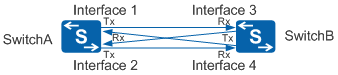
When DLDP is enabled, interfaces in Up state enter the Active state and send Advertisement packets with RSY tags to notify neighbors and request neighbor information. The following uses Interface 1 as an example to describe the detection process:
When receiving an Advertisement packet with the RSY tag from Interface 4, Interface 1 regards that it has detected a neighbor. Interface 1 starts the echo timer, sets up a neighbor entry, and starts the entry aging timer. Interface 1 then enters the Probe state and sends probe packets to detect Interface 4.
Interface 4 cannot receive the probe packets from Interface 1, so Interface 1 will not receive echo packets from Interface 4. When the echo timer on Interface 1 times out, Interface 1 enters the Disable state.
The detection process on other interfaces is similar to that on Interface 1. At last, the four interfaces enter the Disable state.
A Link Changes from Bidirectional to Unidirectional After DLDP Is Enabled
As shown in Figure 2, optical fibers connect switches.
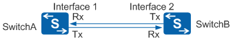
When the Tx and Rx optical fibers are working properly, Switch A and Switch B establish a bidirectional relationship as follows:
When DLDP is enabled, Interface 1 in Up state enters the Active state and sends Advertisement packets with RSY tags to notify neighbors and request neighbor information.
When receiving an Advertisement packet with the RSY tag from Interface 1, Interface 2 regards that it has detected a neighbor. Interface 2 then starts the echo timer, sets up a neighbor entry, and starts the entry aging timer. Interface 2 enters the Probe state and sends a probe packet.
Upon receiving the probe packet, Interface 1 sets up a neighbor entry, enters the Probe state, and returns an echo packet to Interface 2.
When Interface 2 receives the echo packet, it finds that the neighbor entry exists, and the information about the neighbor carried by the echo packet is the same as that saved on the local device. Interface 2 marks the connection with this neighbor as bidirectional.
Interface 2 transitions from the Probe state to the Advertisement state, and periodically sends Advertisement packets. Interface 2 in Advertisement state resets the aging timer for a known neighbor each time a packet is received from the neighbor.
The process for sending Advertisement packets from Interface 2, and setting up a neighbor on Interface 1, is similar to steps 1 to 4 in the preceding explanation. Once these processes have been completed, Interface 1 and Interface 2 regard each other as neighbors with a bidirectional connection. In Figure 3, the Rx optical fiber of Interface 2 has failed and cannot receive an optical signal. When this occurs, Interface 2 enters the Inactive state and stops sending and receiving packets. The Tx optical fiber of Interface 2 remains normal, so Interface 1 can receive signals and remain in Up state. Interface 1 cannot receive DLDPDUs from Interface 2 before the entry aging timer phases out.
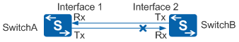
Normal mode: Interface 1 deletes the neighbor entry, enters the Active state, and sends an Advertisement packet with the RSY tag when the entry aging timer times out. After 5 seconds in Active state, Interface 1 enters the Advertisement state. Then Interface 1 retains in Advertisement state and has no neighbor. Interface 2 retains the Inactive state. In this case, DLDP cannot detect unidirectional links.
Enhanced mode: Interface 1 starts the enhanced timer and echo timer and sends a probe packet to the neighbor when the entry aging timer times out. The Tx optical fiber of Interface 1 is disconnected, making Interface 1 unable to receive the echo packet from Interface 2. When the echo timer times out, Interface 1 enters the Disable state and sends a disable packet to the neighbor. In addition, Interface 1 deletes the neighbor entry and starts the RecoverProbe timer to check whether the Tx optical fiber is restored. Interface 2 retains the Inactive state.
In enhanced mode, Interface 2 is physically Down, but Interface 1 cannot detect the change. DLDP supports the fast Link-Down notification mechanism that can rapidly detect a fault on the link connecting Interface 1 and Interface 2 before the entry aging timer times out. Upon detecting that Interface 2 is Down, the physical layer sends a Link-Down notification packet to Interface 1. When receiving the Link-Down notification packet, Interface 1 enters the Disable state.
The fast Link-Down notification mechanism applies only to the enhanced mode.