EFM Enhancements
In compliance with EFM standards, EFM enhancements are extended EFM functions that include association between EFM and an EFM interface, active/standby extension, and single-fiber fault detection.
Association Between EFM and Interfaces
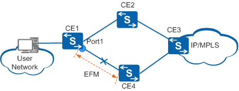
Association between EFM and EFM interfaces can set the associated interface in EFM Down state and trigger an active/standby link switchover, improving transmission quality and reliability.
In Figure 1, CE1 is dual-homed to CE2 and CE4. If the active link between CE1 and CE4 fails, traffic switches to the standby link between CE1 and CE2, minimizing the service interruption time.
Minor link event
Critical link event
EFM negotiation timeout
EFM Active/Standby Extension
The EFM active/standby extension is implemented using the Vendor Specific Info field in the Local Information type-length-value (TLV) of an Information OAMPDU. The value of the Vendor Specific Info field indicates the master or backup state. Figure 2 shows the Vendor Specific Info field in an Information OAMPDU.
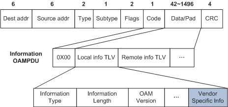
The local device of an EFM connection supports the EFM active/standby extension. The remote device can parse the Vendor Specific Info field (carried in an Information OAMPDU) of the Local Information TLV sent by the local device. Value 0xAB in the Vendor Specific Info field indicates the master state and value 0xBA indicates the backup state. After receiving an Information OAMPDU, the remote device parses the OAMPDU and determines a traffic direction based on the master/backup status carried in the TLV.
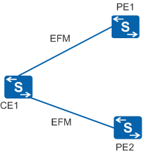
The EFM active/standby extension is used together with EFM association functions to control the traffic direction. EFM can be associated with EFM interfaces and static routes destined for a network. The combination of functions allows traffic to automatically switch to a standby link if an active link fails, ensuring network reliability. In Figure 3, an interface on CE1 is connected to PE1 and another one is connected to PE2. EFM is associated with EFM interfaces or static routes destined for the network on PE1 and PE2. The association allows PE1 and PE2 to monitor active and standby status changes on CE1. If an active/standby interface switchover occurs on CE1, the EFM module notifies PE1 and PE2 of the status change. A traffic switchover is then implemented between PE1 and PE2. This process ensures that the upstream and downstream traffic travel along the same path. Table 1 lists implementation methods of EFM active/standby extension.
Implementation Method |
Description |
|---|---|
EFM active/standby extension used with association between EFM and EFM interfaces |
If the EFM module on a PE detects an active/standby switchover on the SoftX device, the EFM module changes the status of the associated local EFM interface to trigger an active/standby link switchover. The service modules on the associated interface respond to the change by taking specific actions such as re-advertising routes.
|
EFM active/standby extension used together with association between EFM and static routes |
If the EFM module on a PE detects an active/standby switchover on the SoftX device, the EFM module instructs the routing management (RM) module to update the static route that is associated with the EFM module.
|
Single-fiber Fault Detection
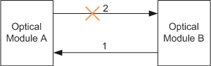
Optical interfaces work in full duplex mode and are considered Up as long as they receive packets even if they fail to send them. This may cause the working and physical statuses of an interface to be inconsistent.
In Figure 4, Optical Module A is directly connected to Optical Module B. If Line 2 is faulty, Optical Module B cannot receive packets and sets its physical status to Down. Optical Module A can still receive packets from Optical Module B over Line 1. Therefore, the physical status of Optical Module A is considered to be Up. If Optical Module A sends packets to Optical Module B, service interruption occurs because Optical Module B cannot receive packets.
EFM single-fiber detection can be used to prevent the preceding problem.
After EFM is associated with an interface, the interface can go Down when EFM detects a single-fiber fault on the interface. EFM enables Layer 2 and Layer 3 services to detect the interface status change and trigger a service switchover. The working status and physical status of the interface remain consistent, preventing service interruption. After the fault is rectified and EFM negotiation succeeds, the interface goes Up and services switch back.
Single-fiber fault detection prevents inconsistency between the working status and physical interface status and allows the service modules to properly detect interface status changes.