Basic Concepts of ERPS
ERPS eliminates loops at the link layer of an Ethernet network. ERPS works for ERPS rings. There are several nodes in an ERPS ring. ERPS blocks the RPL owner port and controls common ports to switch the port status between Forwarding and Discarding and eliminate loops. ERPS uses the control VLAN, data VLAN, and Ethernet Ring Protection (ERP) instance.
On the network shown in Figure 1, SwitchA through SwitchD constitute a ring and are dual-homed to the upstream network. This access mode will cause a loop on the entire network. To eliminate redundant links and ensure link connectivity, ERPS is used to prevent loops.
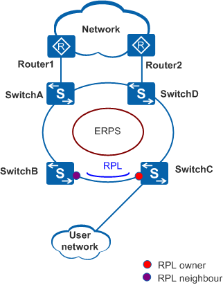
ERPS can be deployed on the network shown in Figure 1.
ERPS Ring
An ERPS ring consists of interconnected Layer 2 switching devices configured with the same control VLAN.
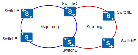
An ERPS ring can be a major ring or a sub-ring. By default, an ERPS ring is a major ring. The major ring is a closed ring, whereas a sub-ring is a non-closed ring. The major ring and sub-ring are configured using commands. On the network shown in Figure 2, SwitchA through SwitchD constitute a major ring, and SwitchC through SwitchF constitute a sub-ring.
Only ERPSv2 supports sub-rings.
Node
A node refers to a Layer 2 switching device added to an ERPS ring. A maximum of two ports on each node can be added to the same ERPS ring. SwitchA through SwitchD in Figure 2 are nodes in an ERPS major ring.
Port Role
RPL owner port
An RPL owner port is responsible for blocking traffic over the Ring Protection Link (RPL) to prevent loops. An ERPS ring has only one RPL owner port.
When the node on which the RPL owner port resides receives an RAPS PDU indicating a link or node fault in an ERPS ring, the node unblocks the RPL owner port. Then the RPL owner port can send and receive traffic to ensure nonstop traffic forwarding.
The link where the RPL owner port resides is the RPL.
RPL neighbor port
An RPL neighbor port is directly connected to an RPL owner port.
Both the RPL owner port and RPL neighbor ports are blocked in normal situations to prevent loops.
If an ERPS ring fails, both the RPL owner and neighbor ports are unblocked.
The RPL neighbor port helps reduce the number of FDB entry updates on the device where the RPL neighbor port resides.
Common port
Common ports are ring ports other than the RPL owner and neighbor ports.
A common port monitors the status of the directly connected ERPS link and sends RAPS PDUs to notify the other ports of its link status changes.
Port Status
Forwarding: forwards user traffic and sends and receives RAPS PDUs.
Discarding: only sends and receives RAPS PDUs.
Control VLAN
A control VLAN is configured in an ERPS ring to transmit RAPS PDUs.
Each ERPS ring must be configured with a control VLAN. After a port is added to an ERPS ring configured with a control VLAN, the port is added to the control VLAN automatically.
Different ERPS rings must use different control VLANs.
Data VLAN
Unlike control VLANs, data VLANs are used to transmit data packets.
ERP Instance
On a Layer 2 device running ERPS, the VLAN in which RAPS PDUs and data packets are transmitted must be mapped to an Ethernet Ring Protection (ERP) instance so that ERPS forwards or blocks the packets based on configured rules. If the mapping is not configured, the preceding packets may cause broadcast storms on the ring network. As a result, the network becomes unavailable.
Timer
Guard timer
After a faulty link or node recovers or a clear operation is executed, the device sends RAPS No Request (NR) messages to inform the other nodes of the link or node recovery and starts the Guard timer. Before the Guard timer expires, the device does not process any RAPS (NR) messages to avoid receiving out-of-date RAPS (NR) messages. After the Guard timer expires, if the device still receives an RAPS (NR) message, the local port enters the Forwarding state.
WTR timer
If an RPL owner port is unblocked due to a link or node fault, the involved port may not go Up immediately after the link or node recovers. Blocking the RPL owner port may cause network flapping. To prevent this problem, the node where the RPL owner port resides starts the wait to restore (WTR) timer after receiving an RAPS (NR) message. If the node receives an RAPS Signal Fail (SF) message before the timer expires, it terminates the WTR timer. If the node does not receive any RAPS (SF) message before the timer expires, it blocks the RPL owner port when the timer expires and sends an RAPS (no request, root blocked) message. After receiving this RAPS (NR, RB) message, the nodes set their recovered ports on the ring to the Forwarding state.
Holdoff timer
On Layer 2 networks running ERPS, there may be different requirements for protection switching. For example, on a network where multi-layer services are provided, after a server fails, users may require a period of time to rectify the server fault so that clients do not detect the fault. You can set the Holdoff timer. If the fault occurs, the fault is not immediately sent to ERPS until the Holdoff timer expires.
WTB timer
The wait to block (WTB) timer starts when Forced Switch (FS) or Manual Switch (MS) is performed. Because multiple nodes on an ERPS ring may be in FS or MS state, the clear operation takes effect only after the WTB timer expires. This prevents the RPL owner port from being blocked immediately.
The WTB timer value cannot be configured. Its value is the Guard timer value plus 5. The default WTB timer value is 7s.
Revertive and Non-revertive Switching
After link faults in an ERPS ring are rectified, re-blocking the RPL owner port depends on the switching mode:
- In revertive switching, the RPL owner port is re-blocked after the WTR timer expires, and the RPL is blocked.
- In non-revertive switching, the WTR timer is not started, and the original faulty link is still blocked.
ERPS rings use revertive switching by default.
ERPSv1 supports only revertive switching. ERPSv2 supports both revertive and non-revertive switching.Port Blocking Modes
- FS: forcibly blocks a port immediately after FS is configured, irrespective of whether link failures have occurred.
- MS: blocks a port on which MS is configured when the ERPS ring is in Idle or Pending state.
- Clears an existing FS or MS operation.
- Triggers revertive switching before the WTR or WTB timer expires in the case of revertive switching operations.
- Triggers revertive switching in the case of non-revertive switching operations.
Only ERPSv2 supports port blocking modes.
RAPS PDU Transmission Mode in a Sub-ring
ERPSv2 supports single-ring and multi-ring topologies. In multi-ring topologies, both the virtual channel (VC) and non-virtual-channel (NVC) can be used to transmit RAPS PDUs in sub-rings.
- VC: RAPS PDUs in sub-rings are transmitted to the major ring through interconnected nodes. The RPL owner port of the sub-ring blocks both RAPS PDUs and data traffic.
- NVC: RAPS PDUs in sub-rings are terminated on the interconnected nodes. The RPL owner port blocks data traffic but not RAPS PDUs in each sub-ring.
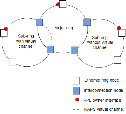
On the network shown in Figure 3, a major ring is interconnected with two sub-rings. The sub-ring on the left has a VC, whereas the sub-ring on the right has an NVC.

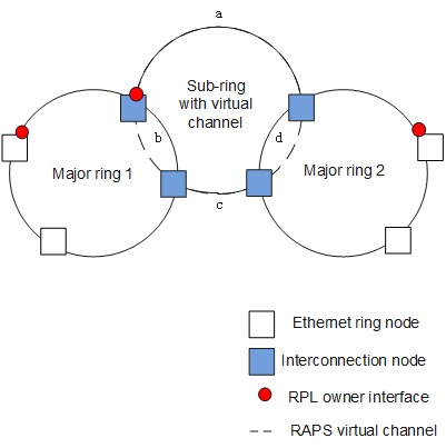
When sub-ring links are discontiguous, VCs must be used.
On the network shown in Figure 4, links b and d belong to major rings 1 and 2 respectively; links a and c belong to the sub-ring. As links a and c are discontiguous, they cannot detect the status change between each other, so VCs must be used for RAPS PDU transmission.
| RAPS PDU Transmission Mode in a Sub-ring | Advantage | Disadvantage |
|---|---|---|
VC |
Applies to scenarios in which sub-ring links are discontiguous. |
Requires VC resource reservation and controls VLAN assignment from adjacent rings. |
NVC |
Does not need to reserve resources or control VLAN assignment from adjacent rings. |
Is not applicable to scenarios in which sub-ring links are discontiguous. |