ERPS Single-ring Principles
ERPS is a standard ring protocol used to prevent loops in ERPS rings at the Ethernet link layer. A maximum of two ports on each Layer 2 switching device can be added to the same ERPS ring.
To prevent loops in an ERPS ring, you can enable a loop-breaking mechanism to block the Ring Protection Link (RPL) owner port to eliminate loops. If a link on the ring network fails, the ERPS-enabled device immediately unblocks the blocked port and performs link switching to restore communication between nodes on the ring network.
This section describes how ERPS is implemented on a single-ring network when links are normal, when a link fails, and when the link recovers (including protection switching operations).
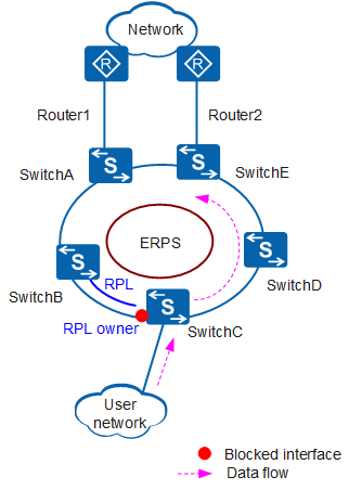
Links Are Normal
- To prevent loops, ERPS blocks the RPL owner port and also the RPL neighbor port (if any is configured). All other ports can transmit service traffic.
- The RPL owner port sends RAPS (NRRB) messages to all other nodes in the ring at an interval of 5s, indicating that ERPS links are normal.
A Link Fails
As shown in Figure 2, if the link between SwitchD and SwitchE fails, the ERPS protection switching mechanism is triggered. The ports on both ends of the faulty link are blocked, and the RPL owner port and RPL neighbor port are unblocked to send and receive traffic. This mechanism ensures nonstop traffic transmission. The process is as follows:
- After SwitchD and SwitchE detect the link fault, they block their ports on the faulty link and update Filtering Database (FDB) entries.
- SwitchD and SwitchE send three consecutive RAPS Signal Fail (SF) messages to the other LSWs and send one RAPS (SF) message at an interval of 5s afterwards.
- After receiving an RAPS (SF) message, the other LSWs update their FDB entries. SwitchC on which the RPL owner port resides and SwitchB on which the RPL neighbor port resides unblock the respective RPL owner port and RPL neighbor port, and update FDB entries.
The Link Recovers
After the link fault is rectified, either of two situations may occur:
- If the ERPS ring uses revertive switching, the RPL owner port is blocked again, and the link that has recovered is used to forward traffic.
- If the ERPS ring uses non-revertive switching, the RPL remains unblocked, and the link that has recovered is still blocked.
The following example uses revertive switching to illustrate the process after the link recovers.
- After the link between SwitchD and SwitchE recovers, SwitchD and SwitchE start the Guard timer to avoid receiving out-of-date RAPS PDUs. The two switches do not receive any RAPS PDUs before the timer expires. At the same time, SwitchD and SwitchE send RAPS (NR) messages to the other LSWs.
- After receiving an RAPS (NR) message, SwitchC on which the RPL owner port resides starts the WTR timer. After the WTR timer expires, SwitchC blocks the RPL owner port and sends RAPS (NR, RB) messages.
- After receiving an RAPS (NR, RB) message, SwitchD and SwitchE unblock the ports at the two ends of the link that has recovered, stop sending RAPS (NR) messages, and update FDB entries. The other LSWs also update FDB entries after receiving an RAPS (NR, RB) message.
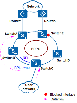
Protection Switching
Forced switch
On the network shown in Figure 3, SwitchA through SwitchE in the ERPS ring can communicate with each other. A forced switch (FS) operation is performed on the SwitchE's port that connects to SwitchD, and the SwitchE's port is blocked. Then the RPL owner port and RPL neighbor port are unblocked to send and receive traffic. This mechanism ensures nonstop traffic transmission. The process is as follows:
- After the SwitchD's port that connects to SwitchE is forcibly blocked, SwitchE update FDB entries.
- SwitchE sends three consecutive RAPS (SF) messages to the other LSWs and sends one RAPS (SF) message at an interval of 5s afterwards.
- After receiving an RAPS (SF) message, the other LSWs update their FDB entries. SwitchC on which the RPL owner port resides and SwitchB on which the RPL neighbor port resides unblock the respective RPL owner port and RPL neighbor port, and update FDB entries.
Clear
After a clear operation is performed on SwitchE, the port that is forcibly blocked by FS sends RAPS (NR) messages to all other ports in the ERPS ring.
- If the ERPS ring uses revertive switching, the RPL owner port starts the WTB timer after receiving an RAPS (NR) message. After the WTB timer expires, the FS operation is cleared. Then the RPL owner port is blocked, and the blocked port on SwitchE is unblocked. If you perform a clear operation on SwitchC on which the RPL owner port resides before the WTB timer expires, the RPL owner port is immediately blocked, and the blocked port on SwitchE is unblocked.
- If the ERPS ring uses non-revertive switching and you want to block the RPL owner port, perform a clear operation on SwitchC on which the RPL owner port resides.
Manual switch
The MS process in an ERPS ring is similar to the FS process. The difference is that the MS operation does not take effect when the ERPS ring is not idle or pending.