ERPS Multi-instance
On a common ERPS network, a physical ring can be configured with a single ERPS ring, and only one blocked port can be specified in the ring. When the ERPS ring is in normal state, the blocked port prohibits all service packets from passing through. As a result, all service data is transmitted through one path over the ERPS ring, and the other link on the blocked port becomes idle, wasting bandwidth. As shown in Figure 1, when only ERPS Ring1 is configured, Interface1 is blocked and data is forwarded through the path where Data Flow1 travels. The link SwitchC -> SwitchD -> SwitchE is idle.
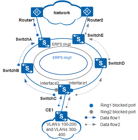
To improve link use efficiency, only two logical rings can be configured in the same physical ring in the ERPS multi-instance. A port may have different roles in different ERPS rings and different ERPS rings use different control VLANs. A physical ring can have two blocked ports accordingly. Each blocked port independently monitors the physical ring status and is blocked or unblocked. An ERPS ring must be configured with an ERP instance, and each ERP instance specifies a range of VLANs. The topology calculated for a specific ERPS ring only takes effect in the ERPS ring. Different VLANs can use separate paths, implementing traffic load balancing and link backup.
As shown in Figure 1, you can configure ERPS Ring1 and ERPS Ring2 in the physical ring consisting of SwitchA through SwitchE. Interface1 is the blocked port in ERPS Ring1. The VLANs mapping to the ERP instance is VLANs 100 to 200. Interface2 is the blocked port in ERPS Ring2. The VLANs mapping to the ERP instance is VLANs 300 to 400. After the configuration is completed, data from VLANs 100 to 200 is forwarded through Data Flow1, and data from VLANs 300 to 400 is forwarded through Data Flow2. In this manner, load balancing is implemented and link use efficiency is improved.