Link Aggregation in LACP Mode
Context
LACP, as specified in IEEE 802.3ad, implements dynamic link aggregation and de-aggregation, allowing LACP-enabled switches at both ends to exchange Link Aggregation Control Protocol Data Units (LACPDUs). LACP provides a standard negotiation mechanism that a Huawei switch can use to create and enable the aggregated link based on its configuration. After an aggregated link is formed, LACP is responsible for maintaining the link. LACP adjusts the link if an aggregated link's status changes.
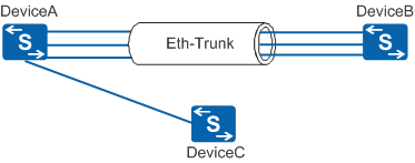
For example, in Figure 1, four interfaces on DeviceA should be connected to the corresponding interfaces on DeviceB, and these interfaces are all bundled into an Eth-Trunk. However, one interface on DeviceA is connected to an interface on DeviceC. As a result, DeviceA may send data destined for DeviceB to DeviceC. In manual mode, this fault would go undetected.
In this case, if LACP is enabled on DeviceA and DeviceB, the Eth-Trunk only selects active links (links connected to DeviceB) to forward data after negotiation. Data sent by DeviceA destined for DeviceB only reaches DeviceB.
Basic Concepts
LACP system priority
LACP system priorities determine the sequence in which devices at two ends of an Eth-Trunk select active interfaces to join a LAG. In order for a LAG to be established, both devices must select the same interfaces as active interfaces. To achieve this, one device (with a higher priority) is responsible for selecting the active interfaces. The other device (with a lower priority) then selects the same interfaces as active interfaces. In priority comparisons, numerically lower values have higher priority.
LACP interface priority
LACP interface priorities affect which interfaces of an Eth-Trunk are selected as active interfaces. A smaller numerical value represents a higher priority. The interfaces with the highest LACP interface priority become active interfaces.
M:N backup of member interfaces
LACP mode is also called M:N mode, where M refers to the number of active links and N refers to the number of backup links. This mode guarantees high reliability and allows traffic to be load balanced among M active links.
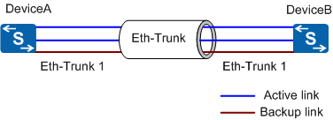
In Figure 2, M+N links with the same attributes (in the same LAG) are set up between two devices. When data is transmitted over the aggregated link, traffic is load balanced among M active links, with no data transmitted over N backup links. Therefore, the actual bandwidth of the aggregated link is the sum of the M links' bandwidth, and the maximum bandwidth of the aggregated link is the sum of the (M+N) links' bandwidth.
If one of the M links fails, LACP selects one of the N backup links to replace the faulty link. The actual bandwidth of the aggregated link is still the sum of M links' bandwidth, but the maximum bandwidth of the aggregated link is the sum of the (M+N-1) links' bandwidth.
M:N backup is mainly applied in situations where the bandwidth of the M links must be assured and a fault tolerance mechanism is required. If an active link fails, the system selects the backup link with the highest priority as the active link.
If no available backup link is found and the number of active links is smaller than the lower threshold, the system shuts down the LAG.
Implementation of Link Aggregation in LACP Mode
LACP-enabled switches exchange LACPDUs. An LACPDU contains the LACP system priority, MAC address, LACP interface priority, interface number, and operational key.

An Eth-Trunk in LACP mode is set up as follows:
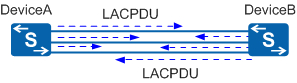
After member interfaces are added to an Eth-Trunk in LACP mode, both ends send LACPDUs.
In Figure 3, create an Eth-Trunk in LACP mode on DeviceA and DeviceB and add member interfaces to the Eth-Trunk. Then enable LACP on the member interfaces. Both devices can then exchange LACPDUs.
Devices at both ends determine the Actor and active links.
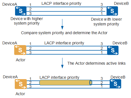
In Figure 4, when DeviceB receives LACPDUs from DeviceA, DeviceB checks and records information about DeviceA and compares LACP system priorities. If the LACP system priority of DeviceA is higher than that of DeviceB, DeviceA becomes the Actor. If DeviceA and DeviceB have the same LACP system priority, the device with a smaller MAC address becomes the Actor.
After the Actor is selected, both devices select active interfaces based on the interface priorities of the Actor. If priorities of interfaces on the Actor are the same, interfaces with smaller interface numbers are selected as active interfaces. An Eth-Trunk is established when both devices select the same interfaces as active interfaces. Active links then load balance traffic.
Other Functions in LACP Mode
LACP preemption
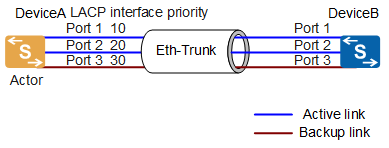
In Figure 5, Port 1, Port 2, and Port 3 are member interfaces of an Eth-Trunk; DeviceA acts as the Actor; the upper threshold for the number of active interfaces is 2; LACP priorities of Port 1, Port 2, and Port 3 are 10, 20, and 30 respectively. When LACP negotiation is complete, Port 1 and Port 2 are selected as active interfaces because their LACP priorities are higher, and Port 3 is used as the backup interface.
When LACP preemption is enabled, interfaces with higher priorities in a LAG always function as active interfaces. LACP preemption is used in the following scenarios:
- Port 1 becomes faulty, causing Port3 to take its place and transmit traffic. When Port 1 recovers, if LACP preemption is not enabled on the Eth-Trunk, Port 1 remains in backup state. If LACP preemption is enabled on the Eth-Trunk, after Port1 recovers, it becomes active again due to having a higher priority than Port3, which reverts to being the backup interface.
- With LACP preemption enabled, setting a higher LACP priority for Port 3 will allow it to replace Port 1 or Port 2 as an active interface without either of them first becoming faulty. If LACP preemption is not enabled, the system does not re-select active interfaces even if the priority of a backup interface is set higher than that of an active interface.
LACP preemption delay
The LACP preemption delay is the time a backup link waits before becoming the active link after an active link becomes faulty. The LACP preemption delay is used to prevent unstable data transmission over an Eth-Trunk link caused by frequent status changes of member links.
In Figure 5, Port 1 becomes inactive due to a link fault, which then recovers. If LACP preemption is enabled and the LACP preemption delay is set, Port 1 becomes active again only after the LACP preemption delay.
Switchover between active and inactive links
In LACP mode, a link switchover in a LAG is triggered if a device at one end detects one of the following events:
An active link goes Down.
Ethernet OAM detects a link fault.
LACP detects a link fault.
An active interface becomes unavailable.
When LACP preemption is enabled, a backup interface becomes the active interface as soon as its priority is changed to be higher than that of the current active interface.
When any of the preceding events occurs, LACP takes effect with the following sequence of events:
Shuts down the faulty link.
Selects the backup link with the highest priority among N backup links to replace the faulty active link.
The backup link with the highest priority becomes the active link and begins forwarding data.