Basic Concepts of BGP/MPLS IP VPN
Site
The following describes different aspects of a site.
A site is a group of IP systems with IP connectivity, which can be achieved independent of SP networks.
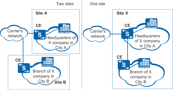
Figure 1 shows examples of sites.
In Figure 1 (left side network), the Headquarters of X company in City A is a site, and the Branch of X company in City B is another site. IP devices communicate within each site without using the carrier network.
Sites are configured based on topologies between devices but not their geographic locations. Devices in a site are typically geographically adjacent to each other. Two geographically separated IP systems also compose a site if they are connected through leased lines and communicate without the use of a carrier network.
In Figure 1 (right side network), the Branch network in City B connects to the Headquarters network in City A through leased lines but not a carrier network. The branch and headquarters networks compose a site.
Devices in a site may belong to multiple VPNs.
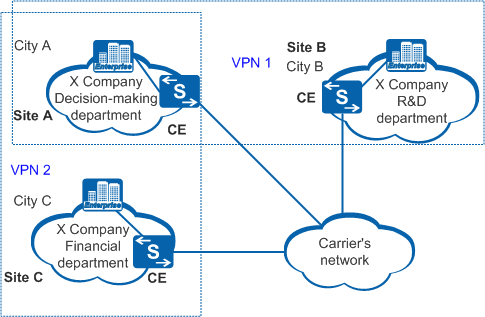
Figure 2 shows an example of one site that belongs to two VPNs.
In Figure 2, the Decision-making department of X company in City A (Site A) is allowed to communicate with the R&D department in City B (Site B) and the Financial department in City C (Site C). Site B and Site C are not allowed to communicate with each other. Two VPNs, VPN 1 and VPN 2, can be established in this case. Site A and Site B belong to VPN 1; Site A and Site C belong to VPN 2. Site A belongs to both VPNs.
A site connects to a carrier network through CE devices. A site may have more than one CE device, but a CE device belongs to only one site.
A CE device is selected if a site:
Is a host; the host is the CE device of the site.
Is a subnet; switches are used as CE devices.
Has multiple subnets; routers are used as CE devices.
Sites connected to the same carrier network can be grouped into different sets using policies. Only sites in the same set, such as a VPN, communicate with each other through the carrier network.
Address Space Overlapping
Each VPN manages an address space and different VPN address spaces may overlap. For example, if both VPN1 and VPN2 use addresses on the network segment 10.110.10.0/24, their address spaces overlap.
VPNs use overlapping address spaces in the following situations:
Two VPNs do not cover the same site.
Two VPNs cover the same site, but devices in this site do not need to communicate with other devices using overlapping address spaces.
VPN Instance
In BGP/MPLS IP VPN implementation, different VPN routes are isolated by VPN instances.
A PE device establishes and maintains a VPN instance for each directly connected site. A VPN instance contains VPN member interfaces and routes of the corresponding site. Information about a VPN instance includes the IP routing table, label forwarding table, interface bound to the VPN instance, and VPN instance management information. VPN instance management information includes the route distinguisher (RD), route filtering policy, and member interface list of the VPN instance.
- A VPN consists of multiple sites. A site may belong to multiple VPNs.
- A site is associated with a VPN instance on a PE device. A VPN instance integrates VPN members and routing policies of associated sites. Multiple sites compose a VPN based on rules of the VPN instance.
- VPN instances are not mapped to VPNs on a one-to-one basis, whereas VPN instances are mapped to sites on a one-to-one basis.
A VPN instance is also called a VPN routing and forwarding table (VRF). A PE device has multiple routing and forwarding tables, including a public routing and forwarding table and one or more VRFs. Figure 3 shows a networking example of VPN instances.
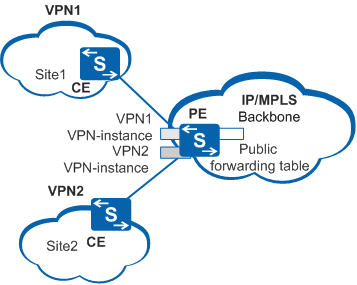
A public routing and forwarding table and a VRF differ in the following ways:
A public routing table contains IPv4 routes of all PE and P devices. The routes are static or dynamic routes generated by routing protocols on the backbone network.
A VPN routing table contains routes of all sites that belong to a VPN instance. The routes are obtained through the exchange of VPN routing information between PE devices or between CE and PE devices.
Information in a public forwarding table is extracted from the public routing table according to route management policies, whereas information in a VPN forwarding table is extracted from the corresponding VPN routing table.
VPN instances on a PE device are independent of each other and maintain a VRF, which is independent of the public routing and forwarding table.
Each VPN instance can be considered a virtual device that maintains an independent address space and connects to VPNs through interfaces.
RD and VPN-IPv4 Address
Traditional BGP cannot process VPN routes with overlapping address spaces. For example, VPN1 and VPN2 use addresses on the network segment 10.110.10.0/24, and each advertises a route to this network segment. The local PE device identifies routes based on VPN instances. When the routes are advertised to the remote PE device, however, BGP only selects one of the two routes. This is because load balancing is not performed between different VPN routes; the route not chosen by BGP is lost.
PE devices use Multiprotocol Extensions for BGP-4 (MP-BGP) to advertise VPN routes and use VPN-IPv4 addresses to address this issue.
A VPN-IPv4 address has 12 bytes. The first eight bytes represent the RD, and the last four bytes represent the IPv4 address prefix.
Figure 4 shows an example of a VPN-IPv4 address.
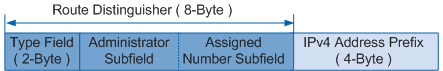
RDs distinguish IPv4 prefixes with the same address space. IPv4 addresses with RDs are VPN-IPv4 addresses (VPNv4 addresses). After receiving IPv4 routes from a CE device, a PE device converts the routes into globally unique VPN-IPv4 routes and advertises these routes on the public network.
SPs can allocate RDs independently because of the RD format. When CE devices are dual-homed to PE devices, the RD must be globally unique to ensure correct routing. Figure 5 shows a networking example of a dual-homed CE device.
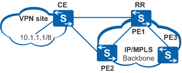
- If the VPN has the same RD on PE1 and PE2, PE3 retains only one VPN-IPv4 route to 10.1.1.1/8 (PE3 -> PE1 -> CE) because the two routes have the same destination address.
- When the direct link between PE1 and CE becomes faulty, PE3 deletes the VPN-IPv4 route to 10.1.1.1/8. VPN data destined for 10.1.1.1/8 cannot be forwarded to the destination, as a result. PE3 has another route to 10.1.1.1/8, PE3 -> PE1 -> PE2 -> CE.
- If the VPN has different RDs on PE1 and PE2, the VPN-IPv4 routes to 10.1.1.1/8 received by PE3 from PE1 have different destination addresses. Therefore, PE3 stores both VPN-IPv4 routes. When any link between PE1 and CE becomes faulty, PE3 deletes the corresponding route and reserves the other route. Data destined for 10.1.1.1/8 can still be correctly forwarded.
VPN Target
A VPN target, also called a route target (RT), is a BGP extension community attribute. BGP/MPLS IP VPN uses VPN targets to control VPN route advertisement.
A VPN instance is associated with one or more VPN target attributes. VPN target attributes are classified into the following types:
Export target: After a PE device learns IPv4 routes from directly connected sites, it converts the routes to VPN-IPv4 routes and sets their export target attribute. The export target attribute is advertised with the routes as a BGP extended community attribute.
Import target: After a PE device receives VPN-IPv4 routes from other PE devices, it checks the export target attribute of the routes. If the export target is the same as the import target of a VPN instance on the local PE device, the local PE device adds the route to the VPN routing table.
BGP/MPLS IP VPN uses VPN targets to control the advertisement and receipt of VPN routes between sites. VPN export targets are independent of import targets. An export target and an import target can be configured with multiple values to implement flexible VPN access control and VPN networking.
For example, if the import target of a VPN instance contains 100:1, 200:1, and 300:1, any route with the export target of 100:1, 200:1, or 300:1 is added to the routing table of the VPN instance.