HVPN
Definition
Most networking designs currently use hierarchical architecture. For example, a metropolitan area network (MAN) typically uses a three-layer architecture consisting of an access layer, an aggregation layer, and a core layer. A BGP/MPLS IP VPN network, however, uses a flat model. All PE devices are located on the same plane. To deploy VPN services in a hierarchical network structure, the flat model of BGP/MPLS IP VPN must be converted into a hierarchical model. The hierarchy of VPN (HVPN) solution assists with this conversion process.
The HVPN solution distributes the functions of one PE to multiple PEs. These PEs playing different roles and form a hierarchical architecture. The HVPN solution is also called the hierarchy of PE (HoPE) solution.
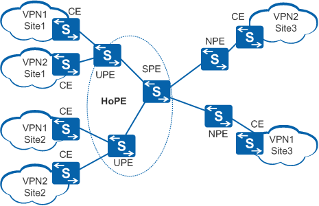
- UPE: directly connected to CEs and provides access services for users.
- SPE: connected to UPEs and located on the core of a network. SPEs manage and advertise VPN routes.
- NPE: connected to SPEs and located on the network side.

The roles of UPEs and SPEs are relative. On an HVPN, a superstratum PE is the SPE of an understratum PE, and an understratum PE is the UPE of a superstratum PE.
An HoPE is compatible with common PEs on an MPLS network.
HVPN can be implemented in HoVPN or H-VPN mode. Both modes implement hierarchical BGP/MPLS IP VPN deployment. Table 1 lists the advantages of HoVPN and H-VPN modes.
Modes |
Characteristics |
Advantages |
|---|---|---|
HoVPN |
An SPE advertises only default or summarized routes to UPEs.
|
As SPEs advertise only default or summarized routes to UPEs, devices that have low route management capabilities can be used as UPEs. Therefore, the HoVPN mode requires lower network deployment cost than the H-VPN mode. |
H-VPN |
An SPE advertises all VPN routes to UPEs.
|
UPEs obtain detailed routes from SPEs. Therefore, the H-VPN mode provides more refined route management and traffic forwarding control than the HoVPN mode. |
Implementation
Label forwarding is used between an SPE and a UPE; only one SPE interface is required to connect to the UPE. The SPE does not need to provide numerous interfaces to connect to users.
MP-IBGP or MP-EBGP can be used between a UPE and an SPE, depending on whether they belong to the same or different ASs. When MP-IBGP is used, an SPE functions as an RR of multiple UPEs to advertise routes between IBGP peers. To reduce the number of routes on the UPEs, avoid using the SPE as an RR for other PEs.
In the following figures, N indicates a next hop, and L indicates a label.
- Route Advertisement on an HVPN Network
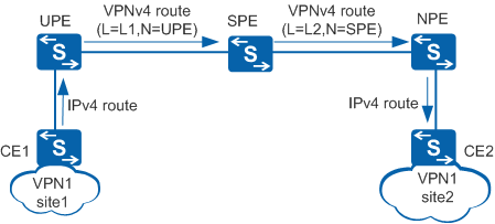
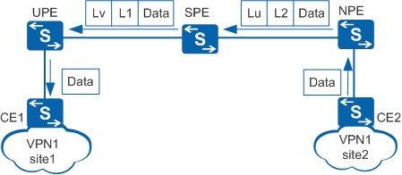
- Route advertisement from CE1 to CE2 (in HoVPN or H-VPN mode)Figure 2 shows route advertisement from CE1 to CE2 in HoVPN or H-VPN mode.
CE1 advertises IPv4 routes to the UPE using the IP protocol.
The UPE applies for label L1 for the received IPv4 routes and converts them to VPNv4 routes. The UPE then sets itself as the next hops of these routes and advertises them to the SPE.
The SPE saves label L1 locally and applies for label L2. The SPE then sets itself as the next hop of these routes and advertises them to the NPE.
The NPE converts these routes to IPv4 routes and imports routes with reachable next hops to its VPN IPv4 routing table. The NPE retains label L2 and iteration tunnel ID information for later packet forwarding.
The NPE advertises the IPv4 routes to CE2 using the IP protocol.
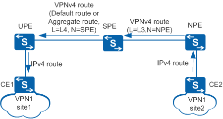
- Route advertisement from CE2 to CE1 (in HoVPN mode)Figure 3 shows route advertisement from CE2 to CE1 in HoVPN mode.
CE2 advertises IPv4 routes to the NPE using the IP protocol.
The NPE applies for label L3 for the received IPv4 routes and converts these routes to VPNv4 routes. The NPE then sets itself as the next hop of these routes and advertises them to the SPE.
The SPE saves label L3 locally and converts these routes to IPv4 routes and imports routes with reachable next hops to its VPN IPv4 routing table.
The SPE imports a default route to its VPN IPv4 routing table or generates a summarized VPN route based on the received IPv4 routes in its VPN IPv4 routing table. The SPE also applies for label L4 for the default route or summarized VPN route. The SPE then converts the default route or summarized VPN route to a VPNv4 route, sets itself as the next hop of the VPNv4 route, and advertises the route to the UPE.
The UPE converts the route to an IPv4 route and imports the route to its VPN IPv4 routing table if the next hop of the route is reachable.
The UPE advertises the IPv4 route to CE1 using the IP protocol.
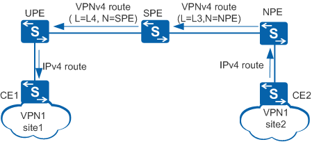
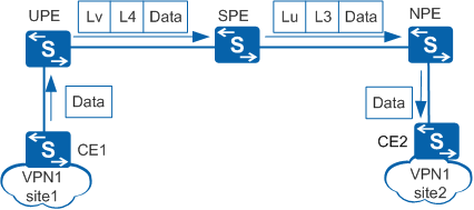
- Route advertisement from CE2 to CE1 (in H-VPN mode)Figure 4 shows route advertisement from CE2 to CE1 in H-VPN mode.
CE2 advertises IPv4 routes to the NPE using the IP protocol.
The NPE applies for label L3 for the received IPv4 routes and converts these routes to VPNv4 routes. Then, the NPE sets itself as the next hops of these routes and advertises them to the SPE.
The SPE receives the VPNv4 routes, saves label L3 locally, and applies for label L4 for these VPNv4 routes. The SPE then sets itself as the next hop of these routes and advertises them to the UPE.
The UPE converts these routes to IPv4 routes and imports routes with reachable next hops to its VPN IPv4 routing table.
The UPE advertises the IPv4 routes to CE1 using the IP protocol.
- Route advertisement from CE1 to CE2 (in HoVPN or H-VPN mode)
- Packet Forwarding on an HVPN Network
- Packet transmission from CE2 to CE1 (in HoVPN or H-VPN mode)Figure 5 shows packet forwarding from CE2 to CE1 in HoVPN or H-VPN mode.
CE2 sends a VPN packet to the NPE.
The NPE receives the packet and searches its VPN forwarding table for a tunnel to forward the packet based on the destination address. Then, the NPE adds an inner label L2 and an outer label Lu to the packet and sends the packet to the SPE over this tunnel.
The SPE receives the packet and replaces the outer label Lu with Lv and the inner label L2 with L1. Then, the SPE sends the packet to the UPE over the same tunnel.
The UPE receives the packet and removes the outer label Lv, searches for a VPN instance corresponding to the packet based on the inner label L1, and removes the inner label L1 after the VPN instance is found. Then, the UPE searches the VPN forwarding table of this VPN instance for the outbound interface of the packet based on the destination address of the packet and sends a pure IP packet with no label through this outbound interface to CE1.
- Packet transmission from CE1 to CE2 (in HoVPN mode)Figure 6 shows packet forwarding from CE1 to CE2 in HoVPN mode.
CE1 sends a VPN packet to the UPE.
The UPE receives the packet and searches its VPN forwarding table for a tunnel to forward the packet based on the destination address of the packet (the UPE matches the destination address of the packet with the forwarding entry for the default route or summarized route). The UPE then adds an inner label L4 and an outer label Lv to the packet and sends the packet to the SPE over the discovered tunnel.
The SPE removes the outer label Lv and searches for the VPN instance corresponding to the packet based on the inner label L4. The SPE then removes the inner label L4 and searches the VPN forwarding table of the discovered VPN instance for a tunnel to forward the packet based on the destination address of the packet. The UPE adds an inner label L3 and an outer label Lu to the packet and sends the packet to the NPE over the discovered tunnel.
The NPE receives the packet and removes the outer label Lu. The NPE then searches for a VPN instance corresponding to the packet based on the inner label L3 and removes the inner label L3 after the VPN instance is discovered. The NPE then searches the VPN forwarding table of this VPN instance for the outbound interface of the packet based on the destination address of the packet. The NPE sends a pure IP packet (with no label) through the outbound interface to CE2.
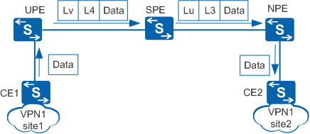
- Packet transmission from CE1 to CE2 (in H-VPN mode)Figure 7 shows packet forwarding from CE1 to CE2 in H-VPN mode.
CE1 sends a VPN packet to the UPE.
The UPE receives the packet and searches its VPN forwarding table for a tunnel to forward the packet based on the destination address of the packet (the UPE matches the destination address of the packet with the forwarding entries for specific routes received from the SPE). The UPE then adds an inner label L4 and an outer label Lv to the packet and sends the packet to the SPE over the discovered tunnel.
The SPE receives the packet and replaces the outer label Lv with Lu and the inner label L2 with L3. The SPE then sends the packet to the NPE over the same tunnel.
The NPE receives the packet and removes the outer label Lu. The NPE searches for a VPN instance corresponding to the packet based on the inner label L3. After the VPN instance is found, the NPE removes the inner label L3. The NPE then searches the VPN forwarding table of this VPN instance for the outbound interface of the packet based on the destination address of the packet. The NPE sends a pure IP packet (with no label) through the outbound interface to CE2.
- Packet transmission from CE2 to CE1 (in HoVPN or H-VPN mode)
HVPE Embedding
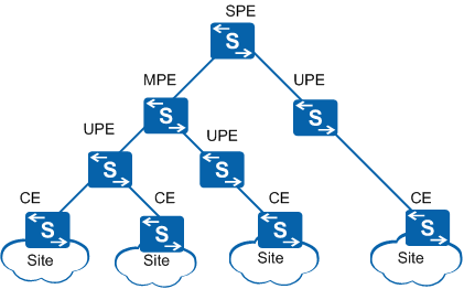
HVPN supports HoPE embedding and can be repeatedly embedded in the two following methods:
An HoPE can function as a UPE and connect to an SPE to form a new HoPE.
An HoPE can function as an SPE and connect to multiple UPEs to form a new HoPE.
HoPE embedding, theoretically, infinitely expands a VPN.
Figure 8 shows a diagram of HoPE embedding. The network has a three-layer H-VPN with the PEs in the middle referred to as middle-level PEs (MPEs). MP-BGP runs between SPE and MPEs and between MPEs and UPEs.
MPE is introduced solely for descriptive purposes and does not actually exist in an H-VPN model.
Benefits of HVPN Networking
HVPN networking provides the following benefits:
Flexible expandability
If UPE performance is insufficient, add an SPE for the UPE to access. If SPE access capabilities are insufficient, add more UPEs to the SPE.
Reduced interface resource requirements
Since a UPE and an SPE exchange packets based on labels, they only need to be connected over a single link.
Reduced burdens on UPEs
A UPE only needs to maintain local VPN routes. Remote VPN routes are represented by a default or summarized route, lightening the burdens on UPEs.
Simple configuration
SPEs and UPEs use MP-BGP, a dynamic routing protocol, to exchange routes and advertise labels. Each UPE only needs to establish a single MP-BGP peer relationship with an SPE.