Traffic Forwarding
Directing Traffic to an MPLS TE Tunnel
- Static Route: applies to networks with simple or stable network topologies.
- Tunnel Policy: applies to scenarios where TE VPN services are transmitted over TE tunnels.
- Auto Route: applies to networks with complex or variable network topologies.
Static Route
The simplest method to direct traffic to an MPLS TE tunnel is to configure a static route and specify a TE tunnel interface as the outbound interface.
Tunnel Policy
- Select-seq policy: selects a TE tunnel to transmit VPN traffic on the public network by configuring an appropriate tunnel selection sequence.
- Tunnel binding policy: binds a TE tunnel to a destination address to provide QoS guarantee.
Auto Route
The auto route feature allows a TE tunnel to participate in IGP route calculations as a logical link. The tunnel interface is used as the outbound interface of the route. The tunnel is considered a point-to-point (P2P) link with a specified metric. Two auto route types are available:
IGP shortcut: An LSP tunnel is not advertised to neighbor nodes, so it will not be used by other nodes.
Forwarding adjacency: An LSP tunnel is advertised to neighboring nodes, so it can be used by these nodes.
Forwarding adjacency allows tunnel information to be advertised based on IGP neighbor relationships.
To use the forwarding adjacency feature, nodes on both ends of a tunnel must be located in the same area.
The following example shows the differences between IGP shortcut and forwarding adjacency.
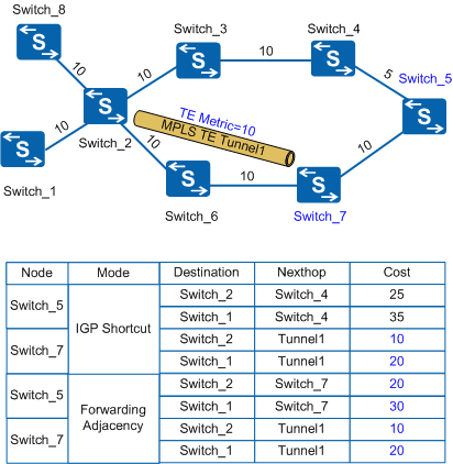
- If auto route is not configured, Switch_5 uses Switch_4 as the next hop, and Switch_7 uses Switch_6 as the next hop.
- If auto route is used:
When Tunnel1 is advertised using IGP shortcut, Switch_5 uses Switch_4 as the next hop, and Switch_7 uses Tunnel1 as the next hop. Because Tunnel1 is not advertised to Switch_5, only Switch_7 selects Tunnel1 using the IGP.
When Tunnel1 is advertised using forwarding adjacency, Switch_5 uses Switch_7 as the next hop, and Switch_7 uses Tunnel1 as the next hop. Because Tunnel1 is advertised to Switch_5 and Switch_7, both the two nodes select Tunnel1 using the IGP.