Understanding Multicast VLAN Replication
Multicast VLAN Replication Based on User VLANs
Switches support the binding between multicast and user VLANs, allowing multicast packet replication in different user VLANs. The user and multicast VLANs can be bound in two modes.
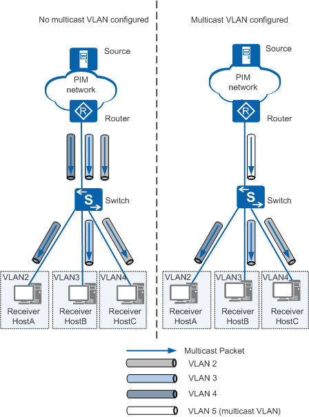
1-to-N multicast VLAN replication
1-to-N multicast VLAN replication is the traditional mode, in which multiple user VLANs can be bound to one multicast VLAN, but a user VLAN can be bound only to one multicast VLAN. This mode provides the key functions of multicast VLAN replication. In Figure 1, the upstream router only needs to copy and send multicast data to the switch configured with multicast VLAN replication. The switch then copies multicast data and sends the data to different user VLANs. This reduces bandwidth consumption between the upstream router and the switch.N-to-N multicast VLAN replication
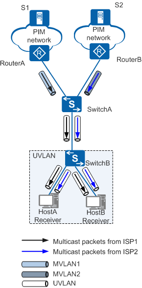
N-to-N multicast VLAN replication is a supplement to the traditional 1-to-N multicast VLAN replication mode. In this mode, a user VLAN is bound to multiple multicast VLANs by configuring a static multicast flow.
In Figure 2, users in a single user VLAN subscribe to multicast services of different ISPs. To differentiate multicast services of different ISPs, each ISP can be assigned a multicast VLAN. After N-to-N multicast VLAN replication is configured, users can receive multicast data from different ISPs.
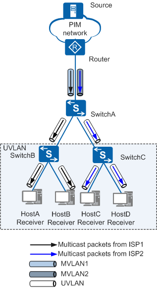
Interface-based Multicast VLAN Replication
Switches support the binding between user and multicast VLANs on user-side interfaces. This allows multicast data to be replicated for different user VLANs and implements interface-based multicast service isolation.
In Figure 3, ISP1 and ISP2 provide multicast services on the network. HostA and HostB obtain multicast services from ISP1, whereas HostC and HostD obtain multicast services from ISP2. To prevent multicast data from being sent to all hosts, the following configuration can be performed: Configure MVLAN1 and MVLAN2 for ISP1 and ISP2, respectively. Bind UVLAN to MVLAN1 on access interfaces of HostA and HostB. Bind UVLAN to MVLAN2 on access interfaces of HostC and HostD. In this way, multicast data provided by ISP1 is sent to HostA and HostB, and multicast data provided by ISP2 is sent to HostC and HostD.