802.1X Authentication
Overview
To resolve wireless local area network (LAN) security issues, the Institute of Electrical and Electronics Engineers (IEEE) 802 LAN/wide area network (WAN) committee developed the 802.1X protocol. Later, the 802.1X protocol was widely applied as a common access control mechanism on LAN interfaces for authentication and security on Ethernet networks.
The 802.1X protocol is an interface-based network access control protocol. It controls users' access to network resources by authenticating the users on access interfaces.
As shown in Figure 1, an 802.1X system uses a standard client/server architecture with three components: client, device, and server.
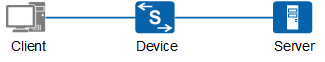
- The client is the entity at an end of the LAN segment and is authenticated by a device at the other end of the link. The client is usually a user terminal. The user initiates 802.1X authentication using client software. The client must support Extensible Authentication Protocol over LAN (EAPoL).
- The device is the entity at an end of the LAN segment, which authenticates the connected client. The device is usually a network device that supports the 802.1X protocol. The device provides an interface, either physical or logical, for the client to access the LAN.
- The authentication server is the entity that provides authentication service for the device. The authentication server carries out authentication, authorization, and accounting on users, and is usually a RADIUS server.
Basic Concepts
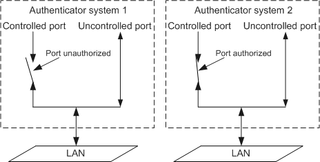
1. Controlled and uncontrolled interfaces
- The uncontrolled interface is mainly used to transmit EAPoL frames in both directions to ensure that the client consistently sends and receives authentication packets.
- In Authorized state, the controlled interface transmits service packets in both directions; in Unauthorized state, the controlled interface cannot receive packets from the client.
2. Authorized and Unauthorized states
The device uses the authentication server to authenticate clients that require LAN access and controls the authorization state (Authorized or Unauthorized) of a controlled interface based on the authentication result (Accept or Reject).
Figure 2 shows the impact of a controlled interface's authorization state on packets capable of passing through the port in two 802.1X authentication systems. The controlled interface in system 1 is in Unauthorized state; the controlled interface in system 2 is in Authorized state.
Authentication Triggering Modes
- Client trigger: The client sends an EAPoL-Start packet to the device to initiate authentication.
- Device trigger: This mode is used when the client cannot send an EAPoL-Start packet, for example, the built-in 802.1X client in the Windows operating system.
Authentication Modes
- The EAP packets transmitted between the client and device are encapsulated in EAPoL format and transmitted across the LAN.
- The device and RADIUS server exchange EAP packets in the following
modes:
- EAP relay: The device relays EAP packets. The device encapsulates EAP packets in EAP over RADIUS (EAPoR) format and sends the packets to the RADIUS server for authentication. This authentication mode simplifies device processing and supports various EAP authentication methods, such as MD5-Challenge, EAP-TLS, and PEAP. However, the RADIUS server must support the corresponding authentication methods.
- EAP termination: The device terminates EAP packets. The device encapsulates client authentication information into standard RADIUS packets, which are then authenticated by the RADIUS server using the Password Authentication Protocol (PAP) or Challenge Handshake Authentication Protocol (CHAP). This authentication mode is applicable since the majority of RADIUS servers support PAP and CHAP authentication and server update is unnecessary. However, device processing is complex, and the device supports only the MD5-Challenge EAP authentication method.

The device supports the following EAP protocols: EAP-CHAP (EAP-MD5), EAP-PAP, EAP-TLS, EAP-TTLS, and EAP-PEAP.
The 802.1X authentication system can complete authentication by exchanging information with the RADIUS server in EAP relay mode and EAP termination mode. Figure 3 and Figure 4 demonstrate both of these authentication modes using the client triggering mode.
1. EAP relay authentication
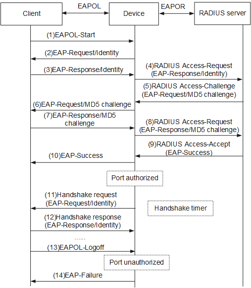
The EAP relay authentication process is described as follows:
When a user needs to access an external network, the user starts the 802.1X client program, enters the applied and registered user name and password, and initiates a connection request. The client then sends an authentication request frame (EAPoL-Start) to the device to start the authentication process.
After receiving the authentication request frame, the device returns an identity request frame (EAP-Request/Identity), requesting the client to send the previously entered user name.
In response to the request sent by the device, the client sends an identity response frame (EAP-Response/Identity) containing the user name to the device.
The device encapsulates the EAP packet in the response frame sent by the client into a RADIUS packet (RADIUS Access-Request) and sends the RADIUS packet to the authentication server for processing.
After receiving the user name forwarded by the device, the RADIUS server searches the user name table in the database for the corresponding password, encrypts the password with a randomly generated MD5 challenge value, and sends the MD5 challenge value in a RADIUS Access-Challenge packet to the device.
The device forwards the MD5 challenge value sent by the RADIUS server to the client.
After receiving the MD5 challenge value from the device, the client encrypts the password with the MD5 challenge value, generates an EAP-Response/MD5-Challenge packet, and sends the packet to the device.
- The device encapsulates the EAP-Response/MD5-Challenge packet into a RADIUS packet (RADIUS Access-Request) and sends the RADIUS packet to the RADIUS server.
- The RADIUS server compares the received encrypted password and the locally encrypted password. If the two passwords match, the user is considered authorized and the RADIUS server sends a packet indicating successful authentication (RADIUS Access-Accept) to the device.
- After receiving the RADIUS Access-Accept packet, the device sends a frame indicating successful authentication (EAP-Success) to the client, changes the interface state to Authorized, and allows the user to access the network using the interface.
- When the user is online, the device periodically sends a handshake packet to the client to monitor the online user.
- After receiving the handshake packet, the client sends a response packet to the device, indicating that the user is still online. By default, the device disconnects the user if it receives no response from the client after sending two handshake packets. The handshake mechanism allows the server to detect unexpected user disconnections.
- If the user wants to go offline, the client sends an EAPoL-Logoff frame to the device.
- The device changes the interface state from Authorized to Unauthorized and sends an EAP-Failure packet to the client.
2. EAP termination authentication
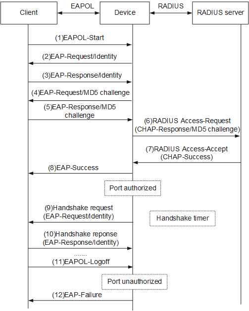
Compared with the EAP relay mode, in EAP termination mode, the device randomly generates an MD5 challenge value for encrypting the user password in Step 4, and sends the user name, the MD5 challenge value, and the password encrypted on the client to the RADIUS server for authentication.
MAC Address Bypass Authentication
MAC address bypass authentication enables authentication using the device MAC address as the user name and password. You cannot install or use 802.1X client software on some devices, such as the printers, in the 802.1X authentication system.
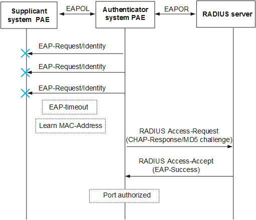
During the 802.1X authentication process, a device first triggers the user to use 802.1X authentication. If the user does not perform 802.1X authentication for a predefined period of time, the user's MAC address is used as the user name and password, and is sent to an authentication server for authentication.
As shown in Figure 5, if the device receives no response after sending multiple authentication requests, MAC address bypass authentication is used.
802.1X Authentication Supports Dynamic VLAN Authorization
1. Guest VLAN
When the Guest VLAN function is enabled, if the user does not respond to the 802.1X request, the device adds the interface where the user resides to the Guest VLAN. For example, this occurs if no 802.1X client software is installed. In this way, the user can access resources in the Guest VLAN, enabling unauthorized users to acquire client software, update client, or perform operations such as user upgrade programs.
2. Restrict VLAN
When the Restrict VLAN function is enabled, if the user authentication fails, the device adds the interface where the user resides to the Restrict VLAN. For example, this occurs if the incorrect user name or password is entered. Similar to the Guest VLAN function, the Restrict VLAN function allows users to access limited network resources before being authenticated. The Restrict VLAN typically limits access to network resources from unauthenticated users more strictly than the Guest VLAN.
3. Critical VLAN
After the Critical VLAN function is enabled, the device adds an interface where the user resides to the Critical VLAN if the authentication server does not respond, for example, because the network between the device and authentication server is disconnected or the authentication server is faulty. In this way, the user can access resources in the Critical VLAN.
802.1X-based Fast Deployment
The NAC solution improves a network's overall defense capabilities, but deploying 802.1X clients can be difficult. 802.1X-based fast deployment can expedite the process. This feature redirects users to the authentication page. The users then can download the client software and install it. To support 802.1X-based fast deployment, 802.1X provides the following two mechanisms:
Limit on accessible network resources
Before 802.1X authentication, an access control list (ACL) is used to allow users to access only a specific IP segment or server. Users can download and upgrade client software or obtain dynamic IP addresses from the specified server.
URL redirection
Before 802.1X authentication, a user using a web browser to access the network is automatically redirected to a specified URL, for example, the client software download page.
User Group Authorization
The device can authorize users based on the user group. After users are authenticated, the authentication server groups users together. Each user group is bound to an ACL so that users in the same user group share an ACL.