Understanding PoE
Introduction to PoE
Power-sourcing Equipment (PSE)
A PSE is a PoE device that provides power to PDs and supports detection, analysis, and intelligent power management.
PD
A PD is a device that receives power from a PSE. Examples of PDs include wireless APs, portable device chargers, POS machines, and cameras. PDs are classified into standard and non-standard PDs depending on whether they conform to IEEE standards.
PoE power supply
A PoE power supply provides power to a PoE system. The number of PDs connected to a PSE is limited by the power output of the PoE power supply. PoE power supplies are classified into built-in and external power supplies depending on whether they are swappable.
PoE Implementation
Procedure |
Item |
Description |
|---|---|---|
1 |
PD detection |
A PSE transmits a low voltage (ranging from 2.7 V to 10.1 V) with a limited current through its interfaces to detect PDs at an interval of 2 seconds. If the PSE detects a resistance between 19 kΩ to 26.5 kΩ, PDs that support IEEE 802.3af or IEEE 802.3at are connected to the PSE. |
2 |
Power supply capability negotiation |
The PSE classifies PDs and negotiates power supply capability. Power supply capability negotiation is classified into two modes: analysis of detected resistance and LLDP Power Capability Negotiation. |
3 |
Power-on start |
In the startup period (often less than 15 microseconds), the PSE starts to provide power to PDs from a low voltage, and increases the voltage until the voltage reaches 48 V DC. |
4 |
Power-on |
After the voltage reaches 48 V DC, the output voltage provided to the PDs is stabilized at 48 V DC, and the power consumption of each PD does not exceed maximum output power of the PSE. |
5 |
Power-off |
While providing power, the PSE continuously detects the input current of a PD. The PSE cuts off the power supply and repeats detection when the current of the PD is reduced to the minimum value or increased sharply in any of the following situations:
|
PoE Power Management Mode
When many PDs are connected to a PSE, the PSE can no longer provide power to all the PDs and needs to manage power supply in automatic or manual mode depending on the power supply mode:
Automatic mode: The PSE automatically powers on or off PDs based on power supply priorities of interfaces. You can set the power supply priority of interfaces to critical, high, or low based on the importance of PDs connected to the interfaces. When the output power approximates to the full capacity of the PSE, the PSE first provides power to the PDs connected to the interfaces of the critical priority and then to those connected to the interfaces of the high priority. If multiple PoE interfaces have the same priority, the S5720-EI and S5720-HI support power to PDs connected to the interfaces in ascending order of interface numbers. Other series of PoE switches provide power to PDs connected to the interfaces in the sequence in which PDs are connected to them.
Manual mode: You can manually power on or off PDs connected to interfaces. In manual mode, the PSE provides power to PDs without considering the priority. Powering on or off a PD connected to a single interface will not affect the power supply status. When the output power approximates to the full capacity of the PSE, the PSE cannot provide power to newly connected PDs.
PoE Perpetual Power Supply and Fast Power-On
Perpetual power supply protects the PDs connected to a PoE device from power failures when the PoE device restarts without being powered off using the reboot command or has the software version upgraded.
Fast power-on shortens the power failure time of the PDs when the PoE device restarts due to a power failure. This is because the PoE device continues to supply power to the PDs immediately after being powered on without waiting until it finishes restarting. Only the S5720-28X-PWH-LI-AC, S5720-16X-PWH-LI-AC, S5720I-12X-PWH-SI-DC, S5730-SI, S5730S-EI, S5730-HI, S5735-L, S5735S-L, S5735S-L-M, S5735-S, S5731-H, S5731S-H, S5731-S, S5731S-S, S5732-H, and S6720-SI support PoE fast power-on.
Power Supply Mode of PSEs
- In midspan PSEs, the PoE module is installed outside of the device.
- In endpoint PSEs, the PoE module is integrated into the device.
Huawei PSEs are endpoint devices. Endpoint PSEs are more widely used than midspan PSEs and are compatible with 2.5GE Base-T, 1000Base-T, 100Base-TX, and 10Base-T interfaces.
In Alternative A mode, power is transmitted over pairs of lines that transmit data.
The PSE provides power to the PD over copper line pairs connected to pins 1 and 2 and pins 3 and 6. Pins 1 and 2 use the negative voltage and pins 3 and 6 use the positive voltage.
10Base-T and 100Base-TX interfaces use copper line pairs connected to pins 1 and 2 and pins 3 and 6 to transmit data, and 1000Base-T interfaces use four line pairs to transmit data.
DC power and data frequency are independent. Therefore, power and data can be transmitted over a single pair of lines.
In Alternative B, power is transmitted over idle pairs of lines.
The PSE provides power to the PD over copper line pairs connected to pins 4 and 5 and pins 7 and 8. Pins 4 and 5 use the positive voltage and pins 7 and 8 use the negative voltage.
In general, standard PDs must support both modes, whereas PSEs only need to support one mode. The S5720-14X-PWH-SI-AC, S5720-16X-PWH-LI-AC, S5720-28X-PWH-LI-AC, S5720I-SI, S5730-HI, S5732-H, and S6720-SI provide PoE++ power supply and support both Alternative A and Alternative B. Other models support only Alternative A.
MultiGE Electrical Interfaces of PoE Devices Supporting the Maximum Transmission Distance of 200 m
- Huawei uses shielded network cables to support a maximum transmission distance of 200 m. This is because the crosstalk between copper cables is serious when unshielded network cables are bundled together, which has the largest impact on the SNR. Shielded network cables can be used to optimize SNR parameters.
- Huawei tests the anti-interference capability of the PHY chips provided by vendors to ensure that each PHY chip supports a maximum transmission distance of 200 m. Additionally, Huawei enables vendors to customize PHY driver software according to Huawei's requirements to optimize SNR parameters over a long transmission distance.
- Huawei improves various signal attenuation indicators of connectors used by interfaces that support a maximum transmission distance of 200 m to optimize SNR parameters.
- Cabling from PHY chips to interface connectors must be well designed to avoid the crosstalk between interfaces. To enable interfaces to provide a maximum transmission distance of 200 m, Huawei poses specific requirements on the cabling.
LLDP Power Capability Negotiation
Devices analyze the current transmitted between a PSE and PDs to classify PDs. The device supports Link Layer Discovery Protocol (LLDP) power capability negotiation.
IEEE 802.1ab defines the optional Power via MDI Type-Length-Value (TLV). The Power via MDI TLV is encapsulated in LLDP packets, and is used for discovery and advertisement of MDI power capabilities, and network management. When the PSE detects a PD, the PSE and PD periodically send LLDP packets with the defined TLV to each other. The peer end records the information in LLDP packets for information exchange.
However, the Power via MDI TLV defined by IEEE 802.1ab can only meet the requirements of IEEE 802.3af and IEEE 802.3at standards. To comply with the IEEE 802.3bt standard, Huawei defines a Power via MDI TLV format.
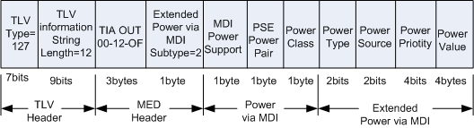
IEEE 802.1ab-Defined Power via MDI TLV
The Power via MDI TLV defined by IEEE 802.1ab is composed of a two-byte packet header and 12-byte TLV information field, as shown in Figure 1.
The following tables describe fields within TLV packets.
MDI Power Support
Bit
Function
Description
0
Specifies the port type.
1: PSE-side port.
0: PD-side port.
1
Indicates whether the PSE supports MDI power supply.
1: indicates that the PSE supports MDI power supply.
0: indicates that the PSE does not support MDI power supply.
2
Specifies the MDI power supply status of the PSE.
1: enabled.
0: disabled.
3
Indicates whether the PSE can control the line pairs.
1: indicates that the PSE can control the line pair.
0: indicates that the PSE cannot control the line pair.
4-7
Reserved.
-
- PSE Power Pair:
1: Alternative A
An endpoint PSE uses line pairs connected to pins 1 and 2 and pins 3 and 6 for power supply.
2: Alternative B
An endpoint PSE uses line pairs connected to pins 4 and 5 and pins 7 and 8 for power supply.
Power Class
Class
Reference Power (Unit: W)
0
15.4
1
4
2
7
3
15.4
4
30
5
45
6
60
7
75
8
90
Power Type, Power Source, and Power Priority
Field
Functions
Description
Power Priority
Specifies the power supply priority of an interface.
11: indicates the lowest priority.
10: indicates the secondary highest priority.
01: indicates the highest priority.
NOTE:This field contains four bits. The two left-most bits are reserved for the system.
Power Source
Specifies the power supply source.
PD:- 11: indicates the PSE and local source.
- 10: needs to be reserved.
- 01: indicates the PSE.
PSE:- 11: indicates to be reserved.
- 10: indicates the backup power supply.
- 01: indicates the primary power supply.
Power Type
Specifies the power supply type.
11: indicates the PD that does not support IEEE 802.3at.
10: indicates the PSE that does not support IEEE 802.3at.
01: indicates the PD that supports IEEE 802.3at.
00: indicates the PSE that supports IEEE 802.3at.
Power Value
It contains PD requested power value and PSE allocated power value. When the PoE power is sufficient, the two values are the same. The value is an integer that ranges from 1 to 255. Exchange power = 0.1 x decimal value of the field. For example, if the value of the field is 255, the exchange power is 25.5 W.
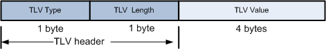
Huawei-defined Power via MDI TLV
The Power via MDI TLV defined by Huawei is composed of a two-byte packet header and four-byte TLV information field, as shown in Figure 2.
The following describes fields within TLV packets.
- TLV Type: indicates the TLV type. This field occupies one byte. The value 1 indicates the power supply mode supported by the PD. The value 2 indicates the current power supply mode of the PD.
- TLV Length: indicates the length of the TLV information field. This field occupies one byte. The value 4 indicates that the TLV information field occupies four bytes.
- TLV Value: indicates the TLV value. This field occupies 4 bytes and is composed of 32 bits. The following describes the meanings of the bits 0, 1, 2, and 3. The bits from 4 to 31 are reserved.
Bit
Description
0
1: IEEE 802.3af is supported or the PD currently works in IEEE 802.3af power supply mode.
0: IEEE 802.3af is not supported or the PD currently does not work in IEEE 802.3af power supply mode.
1
1: IEEE 802.3at is supported or the PD currently works in IEEE 802.3at power supply mode.
0: IEEE 802.3at is not supported or the PD currently does not work in IEEE 802.3at power supply mode.
2
1: IEEE 802.3bt that provides a maximum of 60 W power is supported, or the PD currently works in IEEE 802.3bt power supply mode that provides a maximum of 60 W power.
0: IEEE 802.3bt that provides a maximum of 60 W power is not supported, or the PD currently does not work in IEEE 802.3bt power supply mode that provides a maximum of 60 W power.
3
1: IEEE 802.3bt that provides a maximum of 90 W power is supported, or the PD currently works in IEEE 802.3bt power supply mode that provides a maximum of 90 W power.
0: IEEE 802.3bt that provides a maximum of 90 W power is not supported, or the PD currently does not work in IEEE 802.3bt power supply mode that provides a maximum of 90 W power.
4 to 31
Reserved.
PoE Technical Specifications
PoE technical specifications vary depending on PoE technologies. You can select the required PoE technology to power on PDs according to PD requirements.
Power Supply Technology |
PoE |
PoE+ |
PoE++ |
|---|---|---|---|
Power supply standard |
IEEE 802.3af |
IEEE 802.3at |
IEEE 802.3bt |
Power supply distance |
100 m |
100 m |
100 m |
Power class |
0-3 |
0-4 |
0-8 |
Maximum current |
350 mA |
600 mA |
1730 mA |
PSE output voltage |
44 V DC-57 V DC |
50 V DC-57 V DC |
50 V DC-57 V DC (Type 3 PSE) 52 V DC-57 V DC (Type 4 PSE) |
PSE output power |
≤ 15400 mW |
≤ 30000 mW |
60000 mW (Type 3 PSE) 90000 mW (Type 4 PSE) |
PD input voltage |
36 V DC-57 V DC |
42.5 V DC-57 V DC |
39.9 V DC-57 V DC |
Maximum PD power |
12950 mW |
25500 mW |
51000 mW (Type 3 PSE) 71300 mW (Type 4 PSE) |
Cable requirements |
Unstructured |
CAT-5e or better |
CAT-5e or better |
Power supply cable pairs |
2 |
2 |
4 |