PWE3 Fundamentals
PWE3 Architecture
PWE3 uses the Label Distribution Protocol (LDP) as the signaling protocol, and transmits Layer 2 packets of Customer Edges (CEs) through tunnels such as MPLS LSPs, Generic Routing Encapsulation (GRE) tunnels, or multiprotocol label switching traffic engineering (MPLS TE) tunnels. As shown in Figure 1, PWE3 uses the following entities:
Attachment circuit (AC)
Pseudo wire (PW)
Forwarder
Tunnels
PW signaling protocol
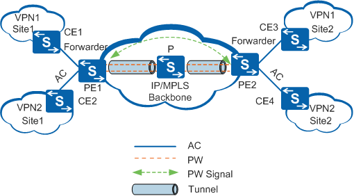
The following uses the flow direction of VPN1 packets from CE1 to CE3 as an example to show the basic direction of data flows.
CE1 sends Layer 2 packets to PE1 through an AC.
After PE1 receives the packets, the forwarder selects a PW to forward the packets.
PE1 generates double MPLS labels (private and public network labels) based on the forwarding entry of the PW. The private network label is used to identify the PW, and the public network label identifies the tunnel to PE2 on the public network.
After Layer 2 packets arrive at PE2 through the tunnel on the public network, the Penultimate Hop Popping (PHP) device (a P device) pops out the public network label, and PE2 pops out the private network label.
The forwarder of PE2 selects an AC to forward the Layer 2 packets to CE3.
PWE3 Classification
PWs are classified into the following types:
Static PW and dynamic PW in terms of implementation
Martini VLL uses LDP to establish dynamic PWs. PWE3 also allows static PWs established using the manually configured PW information.
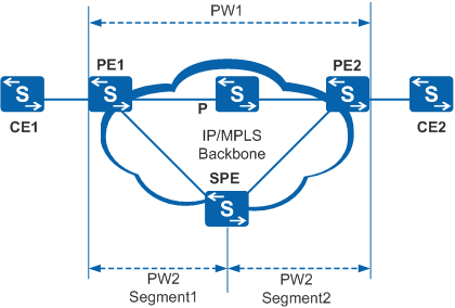
Single-segment PW and multi-segment PW in terms of networking modes
Single-segment PW: Only one PW is set up between two PEs, and PW label switching is not required. For example, PW1 in Figure 2 is a single-segment PW.
Multi-segment PW: Multiple segments of the PW exist between two PEs. The forwarding mechanism of PEs on the multi-segment PW is the same as that of the single-segment PW. The difference is that PW labels need to be switched on the Switching PE (SPE). For example, PW2 in Figure 2 is a multi-segment PW.

A multi-segment PW is required if a signaling connection or directly connected tunnel cannot be established between two PEs. With the multi-segment PW, PWE3 makes networking flexible.
The two classification modes are independent of each other. PWE3 supports the mixed PW, that is, a static PW at one end and a dynamic PW at the other end.
Setup, Maintenance, and Teardown of a Dynamic PW
A dynamic PW uses LDP and encapsulates VC information in the type-length-value (TLV) of LDP packets. PEs need to establish an LDP session, and PW labels are allocated in Downstream Unsolicited (DU) mode and retained in liberal label retention mode.
If a P exists between PEs, a remote LDP session is established between the PEs. If PEs are directly connected, a common LDP session is established.
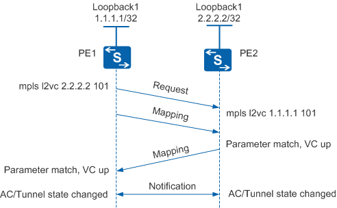
After PWE3 configuration is complete on two PEs of the PW and an LDP session is established between PE1 and PE2, PE1 and PE2 start to establish a dynamic PW, as shown in Figure 3.
PE1 sends a Request message and a Mapping message that contain the local private network label and relevant attributes to PE2.
After receiving the Request message from PE1, PE2 sends a Mapping message to PE1.
After receiving the Mapping message, PE2 checks whether the same PW parameters as those in the Mapping message are configured locally. If the configured PW parameters such as the VC ID, VC type, MTU, and control word status are the same, PE2 sets the local PW in Up state.
After receiving the Mapping message from PE2, PE1 checks whether the locally configured PW parameters are the same as those in the Mapping message. If they are the same, PE1 sets the local PW in Up state. A dynamic PW is set up between PE1 and PE2.
After the PW is set up, PE1 and PE2 send Notification messages to report their status.
When the AC or the tunnel is Down, Martini and PWE3 take different measures:
- Martini sends a Withdraw message to the peer, requesting to tear down the PW. After the AC or tunnel becomes Up, two PEs need to perform negotiation again to establish a PW.
- PWE3 sends a Notification message to notify the peer that packets cannot be forwarded. The PW is not torn down. When the AC or tunnel becomes Up, PWE3 sends a Notification message to notify the peer that packets can be forwarded.
Both PEs tear down the PW only when the PW configuration is deleted or the signaling protocol is interrupted, for example, the public network or PW is Down. On an unstable network, Notification messages can be sent to prevent repeated PW setup and deletion due to link flapping.
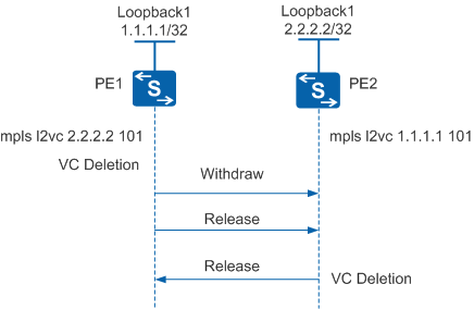
Figure 4 shows the PW teardown process.
- After the PW configuration on PE1 is deleted, PE1 deletes the local VC label and sends Withdraw and Release messages to PE2.
A Withdraw message is used to inform the peer to withdraw labels. A Release message is used to respond to a Withdraw message and request the peer to send a Withdraw message to withdraw labels. To tear down a PW more quickly, PE1 sends a Withdraw message and a Release message consecutively.
- After receiving Withdraw and Release messages from PE1, PE2 deletes the remote VC label and sends a Release message to PE1.
- After PE1 receives a Release message from PE2, the PW between PE1 and PE2 is torn down.
As shown in Figure 5, one or more SPEs are deployed between two PEs for a multi-segment PW. PE1 and PE2 establish connections with the SPE and the SPE combines two segments of the PW.
During signaling negotiation, the SPE forwards parameters in the Mapping message from UPE1 to UPE2. Similarly, the SPE forwards parameters in the Mapping message from UPE2 to UPE1. If parameters on UPE1 and UPE2 are the same, the PW status becomes Up. Similar to the Mapping message, Release, Withdraw, and Notification messages are transmitted segment by segment.
