PW Redundancy
PW Redundancy Signaling
Conventional PWE3 technology implements one-to-one mapping between ACs and PWs. To remain the original forwarding capability, the PW protection mechanism must ensure that only one PW in the PW redundancy group can be in active state.
RFC specifies the PW Status TLV to transmit the PW forwarding status. The PW Status TLV is transported to the remote PW peer using a Label Mapping or LDP Notification message. The PW Status TLV is a 32-bit status code field. Each bit in the status code field can be set to represent a single failure one time. PW redundancy introduces a new PW status code 0x00000020, indicating that the current PW is in standby state.

Only the VPLSs in PWE3 mode support PW redundancy.
Primary/Secondary and Active/Inactive PWs
PW redundancy defines primary/secondary PWs and active/inactive PWs.
Primary and secondary are used to describe PW forwarding priorities and configurable.
A PE preferentially selects the primary PW when both the primary and secondary PWs are in Active state. Currently, only one secondary PW can be configured for a primary PW, though a bypass PW is also a secondary PW.
Active and inactive are used to describe PW forwarding and operating status and cannot be configured.
Only active PWs are used to forward traffic. The signaling status and configured forwarding priority determine the PW forwarding status. A PW with the highest priority will be selected as the active PW to forward traffic. All the other PWs are in inactive state and cannot be used to forward traffic. Inactive PWs used in the VLL service can be configured to receive traffic.
Operation Modes
PW redundancy operation modes are specified on PEs where primary and secondary PWs have been configured. If the PW redundancy operation mode is not specified, PWE3 FRR will be used.
In PWE3 FRR, a PE locally determines the primary and secondary status of the PWs, of which a remote PE is not informed. PWE3 FRR is implemented on Huawei devices only and is not recommended.
Master/Slave mode:
A PE locally determines the primary and secondary status of the PWs, and uses signaling to inform a remote PE of the status. The PW status is independent of the AC status, and therefore PW and AC failures are isolated.
Independent mode:
On a PE, its PW status is determined by the remote AC status after negotiation procedures. The remote PE then informs the PE of the PW status. If an AC fails and protection switching is triggered, protection switching will also be implemented on the PWs. This mode cannot isolate PW and AC failures.
PW redundancy in independent mode is recommended in PWE3 networking to ensure protection switching.
Protection Switching Mechanism
PW redundancy must be associated with the following AC protection switching mechanism to implement dual-homing protection. Currently, PW redundancy can only be used in the scenario where CEs are asymmetrically connected to PEs.
Negotiation of the Primary/Secondary Status of a PW
The primary/secondary status of PWs is negotiated in the following steps:
The master/backup status of PEs is negotiated.
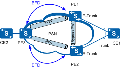
The E-Trunk is responsible for negotiating the master/backup status of PE1 and PE2. Assume that PE1 is the master device and PE2 is the backup device.
The primary/secondary status of PWs is dynamically negotiated.
The E-Trunk is associated with the PWs. In this manner, the E-Trunk can notify the master/backup status of the PEs to the PWs so that the local status of the PWs on PE1 and PE2 can be determined.
PE1 and PE2 notify the local status of the PWs to PE3 through LDP packets.
LDP packets from PE1 and PE2 reach PE3 in a random sequence.
After receiving the LDP packets from PE1 and PE2, PE3 acknowledges that PW1 of PE1 is the primary PW and PW2 of PE2 is the secondary PW.
In this case, the unidirectional traffic path is CE1 -> PE1 -> PW1 -> PE3 -> CE2.
Primary/Secondary PW Switchover
The primary/secondary PW switchover occurs in one of the following situations:
The E-Trunk priority is changed, and the status of PWs is renegotiated.
PE1 becomes faulty. In this case, the E-Trunk detects the fault, and changes the status of PE2 from backup to master. The status of the PWs is then renegotiated.
The status of the PWs will not be renegotiated if the backup node PE2 becomes faulty.
The AC link between PE1 and CE1 becomes faulty. The processing flow is similar to that for the fault of PE1.
The status of the PWs will not be renegotiated if AC link between PE2 and CE1 becomes faulty.
After the primary/secondary PW switchover, the unidirectional traffic path becomes CE1 -> PE2 -> PW2 -> PE3 -> CE2.
After the faulty node or link recovers, the master/backup status of PEs is renegotiated in the E-Trunk. PE1 resumes the master state because its priority is not changed.
Public Network Traffic Protection
When the link between PE1 and PE3 becomes faulty and PW1 goes Down, traffic can be switched through the bypass PW between PE1 and PE2. After detecting the fault, PE3 switches the traffic from PW1 to PW2, and PE1 switches the traffic to the bypass PW. In this case, packets are forwarded through PW2 and the bypass PW, and PE 2 function as a PW switching point (SPE) device.
In this case, the unidirectional traffic path becomes CE1 -> PE1 -> bypass PW -> PE2 -> PW2 -> PE3 -> CE2.
If a protection policy such as TE FRR or LDP FRR is configured on the public network, you do not need to configure the bypass PW.
BFD for mPW
Service PWs and mPWs are configured between PE3 and PE1 and between PE3 and PE2, and the service PWs are associated with the mPWs.
If a large number of service PWs are configured, you can associate these service PWs with the mPW to reduce the number of BFD sessions and save the system resources and link bandwidth.
BFD for mPW can be detected to quickly detect faults on public network links. After detecting a fault, BFD notifies the mPW of the fault. Then, the mPW notifies the service PWs associated with the mPW of the fault. As a result, a primary/secondary switchover is implemented between the service PWs.
PW Revertive Switchover Policy
In the asymmetrical networking of CE dual-homing as shown in Figure 1, after PE3 receives a message informing that the primary PW recovers, PE3 works according to the PW revertive switchover policy.
The PW revertive switchover policies are as follows:
No switchover: Traffic is not switched back to the primary PW.
Immediate switchover: Traffic is immediately switched back to the primary PW.
Delayed switchover: Traffic is switched back to the primary PW after a delay period.
After the revertive switchover, PE3 immediately notifies the peer PE2 on the secondary PW of the fault. In addition, PE3 notifies the peer PE2 on the secondary PW of fault recovery after a delay or immediately, preventing packet loss due to transmission delay between PEs.