QinQ Mapping
Implementation
QinQ mapping is performed after packets are received on the inbound interface and before packets are forwarded through the outbound interface.
Before sending a packet from a local VLAN, a sub-interface replaces the VLAN tag of the packet with a specified VLAN tag.
After receiving a packet, a sub-interface replaces the VLAN tag of the packet with a local VLAN tag.
In real-world applications, QinQ mapping can map customer VLAN (C-VLAN) tags to a service VLAN (S-VLAN) tag to shield different customer VLANs.
New and old sites use conflicting VLAN IDs but new sites need to communicate with old sites.
Sites connected to the public network use conflicting VLAN IDs but do not need to communicate with one another.
The VLAN IDs on one end of the public network different from those on the other end.
1-to-1 mapping
This mode maps the VLAN tag contained in a single-tagged packet received on a sub-interface to a specified tag.
2-to-1 mapping
This mode maps the outer VLAN tag contained in a double-tagged packet received on a sub-interface to a specified tag and leaves the inner VLAN tag intact.
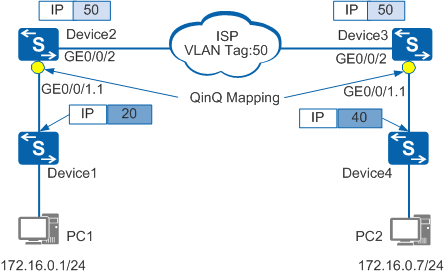
In Figure 1, 1-to-1 QinQ mapping is configured on GE0/0/1.1 interfaces of Device2 and Device3. Frames sent from PC1 to PC2 are processed as follows:
PC1 sends an untagged frame to Device1. After receiving the frame, Device1 adds VLAN tag 20 to the frame.
Device1 forwards the frame with VLAN tag 20 to Device2. Device2 replaces VLAN tag 20 with S-VLAN tag 50 on sub-interface GE0/0/1.1.
Device2 sends the frame with S-VLAN tag 50 through GE0/0/2.
The frame is transparently transmitted on the carrier network.
When the frame arrives at GE0/0/1.1 of Device3, Device3 replaces VLAN tag 50 with VLAN tag 40.
Frames sent from PC2 to PC1 are processed in a similar way.
QinQ mapping allows PC1 to communicate with PC2.
Comparison Between QinQ Mapping and VLAN Mapping
Table 1 compares QinQ mapping and VLAN mapping.
Mapping |
Similarity |
Difference |
|---|---|---|
1-to-1 |
The interface maps the tag in a received single-tagged packet to a specified tag. |
|
2-to-1 |
The interface maps the outer tag of a received double-tagged packet to a specified tag and leaves the inner tag intact. The inner tag is transparently transmitted as service data. |