Understanding Priority Mapping
Priority Mapping
Packets carry different types of precedence field depending on the network type. For example, packets carry the 802.1p field in a VLAN network, the EXP field on an MPLS network, and the DSCP field on an IP network. The mapping between the priority fields must be configured on the gateway to retain packet priorities when the packets traverse different types of networks.
To provide differentiated services for different packets, the switch uses the Differentiated Service (DS) domain to manage and record the mapping between QoS priorities and Class of Service (CoS) values, and the mapping between QoS priorities and colors:
When packets enter the switch, QoS priorities of packets are mapped to internal CoS values (internal or local priorities) and colors.
The switch implements congestion avoidance based on CoS values and colors of packets.
When packets leave the switch, internal CoS values and colors are mapped to QoS priorities. The switch determines the queues that packets enter based on the mapping between internal CoS values and QoS priorities, and performs operations such as traffic shaping, congestion avoidance, and queue scheduling for packets. The switch can re-mark priorities of outgoing packets so that the downstream device can provide differentiated QoS based on packet priorities.
The switch maps QoS priorities to CoS values and colors for incoming packets and maps CoS values and colors to QoS priorities for outgoing packets, as shown in Figure 1.

The CoS represents the service quality of packets in a switch and determines the type of queues to which packets belong. There are eight CoS values, that is, there are eight per-hop behaviors (PHBs). The CoS values in descending order of priority are CS7, CS6, EF, AF4, AF3, AF2, AF1, and BE. For details about PHBs, see PHB.
The color represents the internal drop priority in a switch and determines the sequence in which packets in one queue are dropped when traffic congestion occurs. The Institute of Electrical and Electronics Engineers (IEEE) defines three colors: green, yellow, and red. The drop priority depends on parameter settings.
Precedence Fields
Certain fields in the packet header or frame header record QoS information so that network devices can provide differentiated services. These fields include:
Precedence field
As defined in RFC 791, the 8-bit Type of Service (ToS) field in an IP packet header contains a 3-bit IP precedence field. Figure 2 shows the Precedence field in an IP packet.
Bits 0 to 2 constitute the Precedence field, representing precedence values 7, 6, 5, 4, 3, 2, 1, and 0, in descending order of priority. The high priorities (values 7 and 6) are reserved for routing and network control communication updates. User-level applications can use only priority values 0 to 5.
Apart from the Precedence field, a ToS field also contains the following sub-fields:
Bit D indicates the delay. The value 0 represents a normal delay and the value 1 represents a short delay.
Bit T indicates the throughput. The value 0 represents normal throughput and the value 1 represents high throughput.
Bit R indicates the reliability. The value 0 represents normal reliability and the value 1 represents high reliability.
DSCP field
The ToS field of IP packets was initially defined in RFC 791. RFC 1349 subsequently added bit C to indicate the monetary cost. Then, in RFC 2474, bits 0 to 5 of a ToS field were redefined as the DSCP field, and the ToS field was renamed as the DS field. Figure 2 shows the DSCP field in packets.
In the DS field, the first six bits (bits 0 to 5) are the DS CodePoint (DSCP) and the last two bits (bits 6 and 7) are reserved. The first three bits (bits 0 to 2) are the Class Selector CodePoint (CSCP), which represents the DSCP type. A DS node selects a PHB based on the DSCP value.
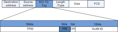
802.1p priority in the Ethernet frame header
Layer 2 devices exchange Ethernet frames. As defined in IEEE 802.1Q, the PRI field (802.1p priority or CoS) in the Ethernet frame header identifies the QoS requirement. Figure 3 shows the PRI field.
The 802.1Q header contains a 3-bit PRI field. The PRI field defines eight service priority values 7, 6, 5, 4, 3, 2, 1, and 0, in descending order of priority.
MPLS EXP field
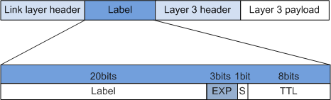
In contrast to IP packets, MPLS packets use labels. A label has 4 bytes. Figure 4 shows the format of the MPLS EXP field.

Only the S5720-EI, S5720-HI, S5730-HI, S5731-H, S5731-S, S5731S-H, S5731S-S, S5732-H, S6720-EI, S6720-HI, S6720S-EI, S6730-H, S6730S-H, S6730-S, and S6730S-S support the MPLS EXP field.
The EXP field contains four sub-fields:Label: contains 20 bits and specifies the next hop to which a packet is to be forwarded.
EXP: contains 3 bits and is reserved for extensions; also known as the CoS field.
S: contains 1 bit and identifies the last entry in the label stack. MPLS supports hierarchical labels. If the S sub-field is 1, the label is at the bottom of the stack.
TTL: contains 8 bits and is the same as the TTL in IP packets.
The EXP field is used as the CoS field in MPLS packets and is equivalent to the ToS field in IP packets. The EXP field is used to differentiate data flows on MPLS networks. The EXP field encodes eight transmission priorities: 7, 6, 5, 4, 3, 2, 1, and 0, in descending order of priority.
On an IP network, the IP precedence or DSCP field in an IP packet identifies the CoS value. On an MPLS network, a Label Switching Router (LSR) cannot identify IP packet headers; therefore, EXP fields are marked at the edge of the MPLS network.
By default, the IP precedence in an IP packet is copied to the EXP field in an MPLS packet at the edge of an MPLS network. If an ISP does not trust a user network or differentiated service levels defined by an ISP are different from those on a user network, reconfigure the EXP field in an MPLS packet based on classification policies and internal service levels. During forwarding on the MPLS network, the ToS field in an IP packet remains unchanged.
On an MPLS network, intermediate nodes classify packets based on the EXP field in MPLS packets and perform congestion management, traffic policing, or traffic shaping.

PHB
An action taken for packets on each DS node is called a PHB. The PHB is a forwarding behavior applied to a DS node. The PHB can be defined based on priorities or QoS specifications such as the delay, jitter, and packet loss rate. The PHB defines some forwarding behaviors but does not specify the implementation mode.
The IETF defines four types of PHBs: Class Selector (CS), Expedited Forwarding (EF), Assured Forwarding (AF), and best-effort (BE). BE is the default PHB.
RFC 2474 classifies CS into CS6 and CS7. RFC 2597 classifies AF into four classes: AF1 to AF4. There are eight classes of PHBs. Each PHB corresponds to a CoS value, and different CoS values determine different congestion management policies. In addition, each PHB is assigned three colors (also called drop priorities): green, yellow, and red. Different colors determine congestion avoidance policies of different flows.
CS
The CS PHB indicates the same service class as the IP precedence value. The CS PHB has the highest priority among standard PHBs.
CS includes CS6 and CS7. By default, CS6 and CS7 PHBs are used for protocol packets, such as STP BPDUs, LLDPDUs, and LACPDUs. If these packets are not forwarded, protocol services are interrupted.
EF
As defined by the EF PHB, the rate at which packets are sent from any DS node must be higher than or equal to the specified rate. The EF PHB cannot be re-marked in the DS domain but can be re-marked on edge nodes.
The EF PHB applies to real-time services that require a short delay, low jitter, and low packet loss rate. Real-time services include video, voice, and video conferencing services.
The EF PHB is used for transmitting VoIP traffic or data flows of enterprise internal video conferences. Voice services require a short delay, low jitter, and low packet loss rate, and are second only to protocol packets in terms of importance.
The bandwidth dedicated to the EF PHB must be restricted so that other services can use the available bandwidth.
AF
As defined by the AF PHB, traffic exceeding the specified bandwidth (as agreed to by users and an ISP) can be forwarded. The traffic that does not exceed the bandwidth specification is forwarded as required, and the traffic that exceeds the bandwidth specification is forwarded at a lower priority.
The AF PHB applies to services that require a short delay, low packet loss rate, and high reliability. Such services include e-commerce and enterprise VPN services.
AF includes AF4, AF3, AF2, and AF1.
The AF4 PHB is used for transmitting signaling traffic of voice services, that is, protocol packets of VoIP services.
Voice signaling is used for call control. A delay of several seconds is tolerable, but no interruption is allowed during a conversation. Therefore, processing of voice traffic must be prioritized ahead of signaling traffic.
The AF3 PHB is used for Telnet and FTP services of remote devices. The services require medium bandwidth, reliable transmission, and zero packet loss, but are sensitive to the delay and jitter.
The AF2 PHB is used for transmitting flows of enterprise IPTV live services and ensures smooth transmission of online video services. Live services are real-time services and require continuous bandwidth and a large throughput guarantee, but allow little packet loss.
The AF1 PHB is used for common data services such as emails. Common data services require only zero packet loss, and do not require high real-time performance and jitter.
BE
The BE PHB focuses only on whether packets can reach the destination, regardless of the transmission performance. All switches must support the BE PHB.
The BE PHB applies to best-effort services on the Internet. Such services include HTTP web page browsing services.