Basic Concepts of RRPP
After an RRPP domain and ring are created, RRPP specifies devices on the ring network as nodes in different roles. Nodes on the ring network detect the ring network status and transmit topology changes by sending, receiving, and processing RRPP packets through primary and secondary interfaces. Nodes on the ring network block or unblock the interfaces based on the ring network status. RRPP can prevent loops when the ring is complete, and rapidly switch service data to the backup link if a device or link fails, ensuring nonstop service transmission.
RRPP Entities
A group of interconnected switches configured with the same domain ID and control VLAN constitute an RRPP domain.
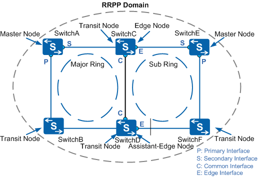
Figure 1 illustrates the entities in an RRPP domain.
RRPP Domain ID
An RRPP domain ID distinguishes an RRPP domain.
RRPP Ring
A physical RRPP ring uses an Ethernet ring topology. An RRPP domain comprises a single ring or multiple interconnected rings. When multiple interconnected rings exist, one ring is the major ring and the others are sub-rings.
An RRPP domain may have multiple sub-rings but only one major ring. The RRPP domain in Figure 1 consists of a major ring and a sub-ring.
RRPP is applied to the networking of a single ring, intersecting rings, and tangent rings. For details about different ring types, see Common RRPP Rings.
Control VLAN and Data VLAN
In an RRPP domain, a control VLAN is used to transmit only RRPP packets, while a data VLAN is used to transmit data packets. The control VLAN is relative to the data VLAN.
When an RRPP domain consists of a major ring and sub-rings, the RRPP domain is configured with two control VLANs: a major control VLAN and a sub-control VLAN. A major control VLAN belongs to the major ring, while a sub-control VLAN belongs to a sub-ring. You only need to specify the major control VLAN. The VLAN whose ID is one greater than the ID of the major control VLAN automatically becomes the sub-control VLAN.
Protocol packets on the major ring are transmitted in the major control VLAN, and RRPP packets on the sub-rings are transmitted in the sub-control VLAN. Protocol packets on the sub-rings are transmitted as data packets on the major ring. For example, in Figure 1, when the secondary interface of the master node on the major ring is blocked, both data packets and protocol packets on the sub-ring must be blocked. When the secondary interface is unblocked, both data packets and protocol packets on the sub-ring are forwarded. Protocol packets on the sub-ring are transmitted as data packets on the major ring, and protocol packets on the major ring are only transmitted on the major ring.
Node
Each device on an RRPP ring is a node. Nodes on the RRPP ring are classified into the following types:
Master node
The master node determines how to handle topology changes. Each RRPP ring must have only one master node.
Any device on an Ethernet ring can serve as the master node.
The master node can be in either Complete or Failed state. The master node status indicates the RRPP ring status.
Transit node
On an RRPP ring, all nodes except the master node are transit nodes. A transit node monitors the status of its directly-connected links and notifies the master node of link changes.
A transit node can be in LinkUp, LinkDown, or Preforwarding state.
When the primary and secondary interfaces of a transit node are Up, the transit node is in LinkUp state. The transit node can receive and forward data packets and RRPP packets.
When the primary or secondary interface of a transit node is Down, the transit node is in LinkDown state.
When the primary or secondary interface of a transit node is Blocked, the transit node is in Preforwarding state and can receive and forward only RRPP packets.
Edge node and assistant edge node
A switch functions as an edge node or an assistant edge node on a sub-ring, and functions as a transit node on the major ring.
On the link where the major ring and sub-ring overlap, if the switch on one intersection point is an edge node, the switch on the other intersection point is an assistant edge node.
A sub-ring has only one edge node and one assistant edge node.
Edge nodes and assistant edge nodes are special transit nodes. They support the same states as transit nodes but differ in the following situations:
If an edge interface is Up, the edge node or assistant edge node is in LinkUp state and can receive and forward data packets and RRPP packets.
If an edge interface is Down, the edge node or assistant edge node is in LinkDown state.
If an edge interface is blocked, the edge node or assistant edge node is in Preforwarding state and can receive and forward only RRPP packets.
If the changes of the link status on the interface of an edge node or assistant edge node causes the state transition, only the edge interface status changes.

The status of the RRPP ring on a node is the status of the node.
Interfaces
Interfaces are classified into the following types:
Primary interface and secondary interface
On both the master node and transit node, one of the two interfaces connected to an Ethernet ring is the primary interface, and the other is the secondary interface. The interface roles depend on the configuration.
The primary and secondary interfaces on the master node provide different functions:
The master node sends Hello packets from its primary interface and receives Hello packets on its secondary interface.
Based on the network status, the master node blocks the secondary interface to prevent loops or unblocks the secondary interface to ensure communication among all the nodes on the ring.
The primary and secondary interfaces on a transit node provide the same function.
Common interface and edge interface
On an edge node or an assistant edge node, an interface shared by the major ring and a sub-ring is called the common interface. An interface used only by a sub-ring is called the edge interface.
The common interface is considered an interface on the major ring and belongs to both the major control VLAN and sub-control VLAN. The edge interface belongs only to the sub-control VLAN.
Common RRPP Rings
- All the devices on a single ring must be configured in the same RRPP domain.
- All the devices on intersecting rings must be configured in the same RRPP domain.
- Devices on two tangent rings must be configured in different RRPP domains. The tangent rings are equal to two single rings and must be configured in two RRPP domains. Each RRPP domain has only one ring.
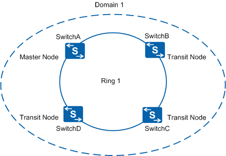
Single Ring
When only a single ring exists in the network topology, you can define one RRPP domain and one RRPP ring. This topology is applicable to simple ring networks and features a quick response to topology changes and short convergence time.
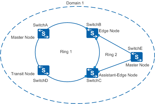
Intersecting Rings
When two or more rings exist in the network topology, and multiple common nodes exist between two neighboring rings, they are considered intersecting rings and you need to define only one RRPP domain. Configure one ring as the major ring and the remaining rings as sub-rings. This topology is applicable when the master node on a sub-ring needs to be dual-homed to the major ring through the edge node and assistant edge node to provide uplink backup.
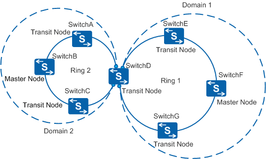
Tangent Rings
When two or more rings exist in the network topology and only one common node exists between two neighboring rings, they are considered to be tangent rings, and you need to configure the rings to belong to different RRPP domains. This topology is applicable to large-scale networks that require domain-based management.