RRPP Multi-Instance
On a common RRPP network, a physical ring contains only one RRPP domain.
When an RRPP ring is in Complete state, the master node blocks the secondary interface, preventing all service packets from passing through. All service packets are transmitted on the RRPP ring along one path. As a result, the link on the secondary interface side of the master node becomes idle, wasting bandwidth. For example, in Figure 1, the link between SwitchA and SwitchC is idle and does not forward data.
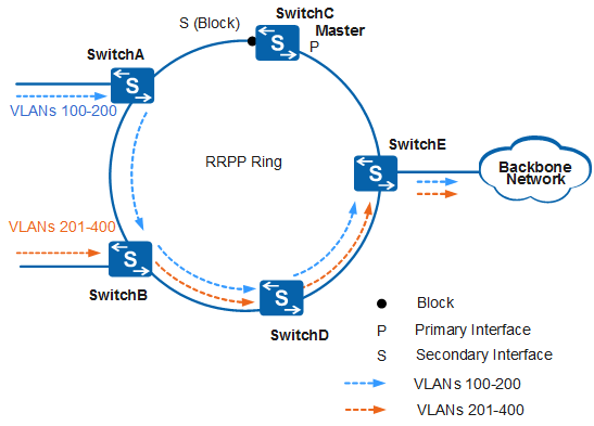
In Figure 1, the devices (SwitchA, SwitchB, SwitchC, and SwitchD) support multiple RRPP domains on one physical ring. An RRPP domain takes effect for data from a protected VLAN associated with the domain. Therefore, you can configure different protected VLANs for each domain. When the master node in a domain blocks its secondary interface, data from protected VLANs in different domains is transmitted through different paths. This allows for link backup and traffic load balancing.

RRPP only takes effect for data from protected VLANs. Loops may occur if data does not belong to the protected VLANs.
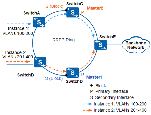
In the example shown in Figure 2, two domains exist on the RRPP multi-instance ring that consists of SwitchA, SwitchB, SwitchC, SwitchD, and SwitchE. SwitchC is the master node in domain 2 and SwitchD is the master node in domain 1.
Instance1 is created in domain 1, and data in VLANs 100 to 200 is mapped to Instance1 and transmitted along the path SwitchA -> SwitchC -> SwitchE. Master2 (SwitchC) serves as the master node in Domain 2. The secondary interface on Master2 is blocked. Only data in VLANs 201 to 400 is blocked and data in VLANs 100 to 200 can pass through.
Instance2 is created in domain 2, and data in VLANs 201 to 400 is mapped to Instance2 and transmitted along the path SwitchB -> SwitchD -> SwitchE. Master1 (SwitchD) serves as the master node in Domain 1. The secondary interface on Master1 is blocked. Only data in VLANs 100 to 200 is blocked and data in VLANs 201 to 400 can pass through.
When a node or link is faulty, each RRPP domain independently calculates the topology and updates forwarding entries on each node.
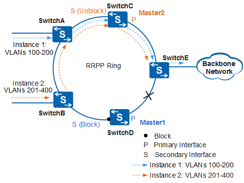
In Figure 3, a fault occurs on the link between SwitchD and SwitchE. This fault does not affect the transmission path for the packets in VLANs 100 to 200 in domain 1, but the transmission path is blocked for the packets in VLANs 201 to 400 in Domain 2.
The master node SwitchC in domain 2 cannot receive Hello packets on the secondary interface. As a result, SwitchC unblocks the secondary interface and requests nodes in domain 2 to update their forwarding entries. After the topology in domain 2 re-converges, the transmission path of the packets in VLANs 201 to 400 changes to SwitchB ->SwitchA ->SwitchC->SwitchE.
After the link between SwitchD and SwitchE recovers, SwitchC receives Hello packets on the secondary interface. As a result, SwitchC blocks the secondary interface and requests nodes in domain 2 to update their forwarding entries. After the topology in domain 2 re-converges, the packets in VLANs 201 to 400 are switched back to the original path SwitchB ->SwitchD ->SwitchE.