Application of RRPP Snooping

Only the S5720-EI, S5720-HI, S5730-HI, S5731-H, S5731S-H, S5732-H, S6720-EI, S6720-HI, S6720S-EI, S6730S-H, and S6730-H support this function.
RRPP snooping notifies a VPLS network of changes on the RRPP ring. After RRPP snooping is enabled on sub-interfaces or VLANIF interfaces, the VPLS network can transparently transmit RRPP packets, detect changes on the RRPP ring, and upgrade forwarding entries, ensuring that traffic can be rapidly switched to a non-blocking path.
In Figure 1, UPEs are connected as an RRPP ring to the VPLS network where NPEs reside. NPEs are connected through a PW, and therefore cannot serve as RRPP nodes to directly respond to RRPP packets. As a result, the VPLS network cannot sense the status change of the RRPP ring. When the RRPP ring topology changes, each node on the VPLS network forwards downstream data according to the MAC address table generated before the RRPP ring topology changes. As a result, the downstream traffic cannot be forwarded.
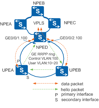
To solve this problem, RRPP snooping can be enabled on the sub-interface or VLANIF interface of NPED and associated with other VSIs on the local device. When RRPP snooping is enabled, if the RRPP ring is faulty, NPED on the VPLS network clears the forwarding entries of the VSIs (including the associated VSIs) on the local node and the forwarding entries of the remote NPEB to re-learn forwarding entries. This ensures that traffic can be switched to a normal path and downstream traffic can be properly forwarded.
In Figure 2, when the link between NPED and UPEA is faulty, and the master node UPEA sends a Common-Flush-FDB packet to request that the transit nodes on the RRPP ring clear their MAC address tables.
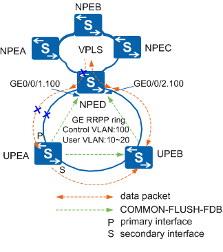
The original MAC address table is not cleared because NPED cannot process the Common-Flush-FDB packet. If downstream service packets are still sent to UPEA, NPED sends the packets to UPEA along the original path. This interrupts the downstream traffic between NPED and NPEA. After UPEB clears the MAC address table, the upstream service packets sent by UPEA are regarded as unknown unicast packets and are forwarded to the VPLS network along the path UPEA -> UPEB -> NPED. After re-learning the MAC address, NPED can forward the downstream traffic destined to UPEA.
When the fault on the RRPP ring is recovered, the master node UPEA sends a Complete-Flush-FDB packet to request that the transit nodes clear their MAC address tables. The downstream traffic between NPED and UPEA is interrupted because NPED cannot process the Complete-Flush-FDB packet.
Figure 3 demonstrates that after RRPP snooping is enabled on sub-interfaces GE0/0/1.100 and GE0/0/2.100 of NPED, NPED can process the Common-Flush-FDB and Complete-Flush-FDB packets.
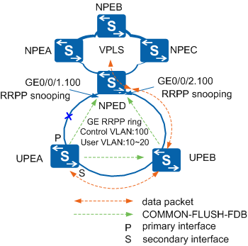
When the RRPP ring topology changes and NPED receives the Common-Flush-FDB or Complete-Flush-FDB packet from the master node UPEA, NPED clears the MAC address table of the VSI associated with sub-interfaces GE0/0/1.100 and GE0/0/2.100. NPED then requests that other NPEs in this VSI clear their MAC address tables.
If the downstream data packets are still sent to UPEA, the packets are regarded as unknown unicast packets and are broadcast in the VLAN and sent to UPEA along the path UPED -> UPEB -> NPEA because NPED cannot find mapping MAC address entries. This ensures downstream traffic continuity.